Network and Distributed Data Acquisition Using Dewesoft NET

With Dewesoft NET, your measurement system can be controlled remotely with the ease of use you couldn't imagine before. Dewesoft NET also serves as the center for Distributed Data Acquisition systems where you have multiple systems located either together or scattered across an entire continent. IRIG and GPS time will take care that data will stay synchronized, no matter how long the acquisition runs.

Dewesoft NET application module provides a nice way to acquire data over the network. This allows us to use multiple systems as one instrument or to acquire data from different locations.

Dewesoft NET application module allows one or more measurement units to be under the control of other computers, named clients. The measurement units and clients must be connected via TCP/IP.

It is important to note that while any channel can be viewed on the clients, the actual data is stored on the measurement units.

Working with Dewesoft-NET is comprised of three basic steps:

  • NET setup - network configurations, appropriate hardware and Dewesoft-NET setup (setting up client and measuring unit, remotely controlling a slave measurement unit)
  • Measurement - creating a display, measuring and acquiring data, and storing this data on a network.
  • Analysis - analyze acquired and stored data on the network, export measured data.


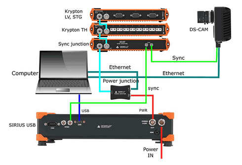
Image 1: Setup the equipment, connect over the Dewesoft NET and start measuring


Dewesoft NET offers three modes of operation:

ModeNumber of Measurement UnitsNumber of Clients
1:111
X:1multiple1
1:X1multiple

With these three modes, almost any application can be covered - from single-channel expansion over the remote control to distributed measurements over hundreds of kilometers - everything is possible.

1:1 Mode - Single measurement unit and a Single client

Image 2: 1:1 operation mode for Dewesoft NET


1:1 mode works with a single measurement system and a single client. In this mode, there are two types of operation

Types of operationDescription
Full remote controlThe client computer acts like a master of the measurement system. When controlling client changes to the setup screen, the measurement system also changes the setup screen. 
View onlyThe measurement system acquires data, while the client computer can connect to it and view the "live" data, but it cannot control the measuring system. A "view client" can only look, but not 'touch'.


X:1 Mode - Multiple measurement units and a Single client

Image 3: X:1 operation mode for Dewesoft NET


Multiple measurement systems and a single client are used in the case of distributed measurements or too high acquisition rates to be managed by a single measurement unit.

The measurement systems have to be synchronized either with hardware clock (one unit is the clock master, the others are slaves) or with the external clock source that is either IRIG or GPS. All measurement systems have to run with the same acquisition rate, in this case, only one connection option is possible - the client is always the master. 

Master client starts and stops the measurement on all units in the measurement network. At any time, the client has access to view mode - but only to one measurement system (one-to-one connection like in single measurement system & single client configuration). Additional view devices are possible, but they can access only a single measurement system.

1:X Mode - Single measurement unit and Multiple clients

Image 4: 1:X operation mode for Dewesoft NET


The third network configuration is to have a single measurement system controlled by one 'master' client and additional 'view' clients.

The master client is able to change the measurement system setup, storing strategy, start and stop measurements, and much more. The view clients are only allowed to take a few channels from the measurement unit (up to the bandwidth limitation) and view and store the data on their local hard disk.

The NET system is always connected via ethernet protocol. This can be obtained in several different ways:

Ethernet protocol connection TypeDescription / Specialty 
Point to point connectionIt is the easiest and most simple configuration of the NET system. On either side, you have a computer (S-box, Minitaur, PC, laptop, ...) with a measurement device (DEWE-43, Sirius, ...) or without it.

With point to point connection, you have an ethernet cable between those two devices. You have to manually set the IP addresses on both sides.
Router
Local network LANThe only limitation is the connection speed.
Internet - WiredDedicated TPC/IP ports need to be opened.
Internet - Wireless


Point to Point Connection: IP Address adjustment

With the point to point connection, we connect two devices with the ethernet cable. We just have to manually set the IP addresses on both sides.

In order to do that, we have to go to Control panel -> Network and Internet -> Network and sharing center.

Image 5: Open Control Panel and select Network and Internet 


We need to select Change adapter settings.

Image 6: Select Change adapter settings 


Right-click on Local connections and select the Properties.

Image 7: Right-click on Ethernet local connection and select the Properties 

In Properties, we choose Internet Protocol Version 4 (TCP/IPv4) and type in the IP address.

Image 8: Select the Internet Protocol Version 4 (TCP/IPv4) and click on the Properties button 


IP addresses on devices must be the same, except for the last number, which must be different (ex. IP address on the first device 192.168.10.1, and the IP address on the second device is 192.168.10.2).

Image 9: Type in IP address 


Now we can connect with the device in Dewesoft X software, measure, and collect data from it. 

There are several possible configurations and setups:

Unit Configuration optionsDescription
Standalone UnitNot networked to anything (the default setting of Dewesoft X upon installation).
Slave Measuring UnitCan measure data under either local control or under the control of a master client.
Master Measuring UnitCan both measure data and control other measurement units (optional).
View ClientCan view data being recorded on the measurement units, but cannot control them.
Master ClientCan control the measurement unit(s) and view their data.

Each measurement unit must be configured as a slave measuring unit in order to utilize the Dewesoft NET software, however, if you are going to use one of your measurement units as the controller for the others, then you should configure that one unit as a master measuring unit.

It is not possible to have more than one "master" within a single Dewesoft NET system, in order to avoid confusion and conflicts.

Searching for the Measurement unit

To activate the appropriate mode for each system within the Dewesoft NET, first run the Dewesoft X and open the Settings menu.

Image 10: Open Dewesoft X software and go in Settings 


Operation mode must be set to Real measurement. To add new devices click the plus button, and then add a new device. Under Dewesoft NET select a Measurement unit, and add it as a device.

Image 11: Set the Real measurement operation mode, click on the plus button, and add a Dewesoft NET Measurement unit 

Now you will see all available measurement units (names, MAC addresses, ...).

Dewesoft Launcher must run on measurement devices so that they can be seen as available units.

Image 12: Now you can see all the available measurement units

Image 13: You can also type in the other system's IP address in the 'Measurement unit name' and connect to it 


It is important to note that by default actual data is stored on the measurement units, even though it can be viewed from the clients. This is critical to protect yourself against data loss which might occur by the network going down or transmission being interrupted. Even if this happens, the data is safely stored on the measurement units. When the network connection is reestablished, it is possible to reconnect automatically.

Even if the network going down or transmission was being interrupted, the data is safely stored on the measurement units. The idea of Dewesoft NET technology is to have a distributed system when:

  • the required computing power is too high for a single measurement unit (many channels sampled with a high sample rate),
  • there is too much distance between the units for analog data transfer,
  • the measurement unit is not accessible (dangerous measurements, test rig measurements, ...),
  • data from measurement units shall be displayed on several client computers,
  • measurements have to be remotely controlled or supervised.


 Principle of the Dewesoft NET data transferImage 14: Principle of the Dewesoft NET data transfer 


Within Dewesoft NET the master client completely controls the slave measurement unit - when the master unit switches to the setup screen, also the slave unit switches to the setup screen.

It is often not possible to transfer all possible channels in real-time to the client for storage, even using a gigabit Ethernet interface.

Imagine even one Dewesoft system with 32 channels, being sampled at 200 kB/s each at 24-bit mode. This is already 25.6 MB/sec, which is more than 200 Mb per second (where each Byte = 8 bits). It does not take long for the network to be completely overloaded with data and be overwhelmed with packet loss.

Immediately after the acquisition is stopped, a button appears on the controlling client allowing the data file(s) to be uploaded from the measurement units for viewing on the client computer.

In the case where your Dewesoft systems are all slave measurement units, you need one master client to control them. Let's assume that we are now sitting at this computer and have Dewesoft X properly installed and ready. Open the Settings menu.

Now use the selector to assign this computer to be the Master client, as shown below:

Image 15: Set one system as a Master client, which will control the other systems 


After confirming the Dewesoft NET setup, the following window will appear:

Image 16: As you exit the Settings with OK, this window will appear where you can connect to the slave measurement unit


Select the Connect button to connect with the measurement unit. After successfully connecting, the measurement unit will be seen as it is shown on the image 16.

You can also change the Channel prefix, and instead of the [Host name] which would in our case be 192.168.10.2, choose for example MU, which stands for a Measuring Unit.

Image 17: After connecting with the measurement unit you will be able to see it under NET tab in a Channel setup


Note that the slave measurement unit called 192.168.10.2 was already found in our example. But if you have not already configured and connected to a measurement unit, just click the Add button and select one or more measurement units in order to add them to the system.

Now click OK to close this dialog and you will notice that the basic Dewesoft X screen has a new addition to the top bar a NET icon:

Image 18: Click on the NET icon and select Show status

Click on the NET icon to show the connection screen. Clicking the Measure bandwidth button in the system will check network performance. In a 100 Mbit network, the transfer speed is about 10 MB/second while Gigabit LAN offers speeds close to 100 MB/second. Please note that the real bandwidth is also limited by system performance.

Image 19: Click on the NET icon to preview the connection screen, where you can also measure the bandwidth

If you want your unit to be set as a slave client, you must first enable remote connections.

Image 20: Enable 'Allow remote connection to this system' on a measurement unit side to set up a slave client


In the example below, the system sees many measurement units on the network, called MU1, MU2, MU3, etc. 

Image 21: Many measurement units coupled together 

Further setup can be done in Master Client Settings:

  • Store data on remote measurement units (checked by default, and highly recommended!)
  • Store data on slave clients 
  • Disable mouse and keyboard on measurement units:
    • If you want to prevent a local operator from changing any settings on the measurement unit or interfering with the test. With this checked, the measurement unit cannot be operated locally, you will have complete control over the client. 
Image 22: Further settings that can be made on a Master Client's side 


In this section you will learn the procedures to control the acquisition from the client:

  • creating a display on the client
  • storing data on the measurement unit
  • transfer stored data to the client
  • NET menu option

Creating a display on client

Before you begin storing, you may want to set up the local display. In previous steps, you may have configured the display of one or more measurement units, but you probably want to see data here, too!

You certainly know how to do this. Go to the Measure mode on the Master client and at the top of your own screen, you have the add Widget button here on the Client to create displays with any combination of channels from any and all measurement units.

As mentioned previously, all measurement units must have a SYNC method in place in order to ensure these three things:

  • truly synchronized data files from multiple measurement units
  • ability to display channels from more than one measurement unit on the client
  • ability to create math channels on the client with channels from more than one measurement unit


Note that the CHANNELS list is now showing channels with the "name" of the MU that they come from automatically. This is so that you know the source of every channel in an easy and convenient way.

Image 23: MU channels are defined for the Measurement Unit, which is in our case the 192.186.10.2 system


In our example, the name of the MU is added in front of the transfer channels.

The channels from each measurement unit will be shown this way automatically. This is the only thing that differs from setting up a screen in the standalone mode of Dewesoft X.

Storing data on the measurement unit

With the client and the measurement unit properly configured, we can now store data. Just click Store in the toolbar in the normal way.

Image 24: Start storing 

Transfer stored data to the client

As soon as the storing is stopped, an important button appears automatically, called Transfer button:

Image 25: In case you are storing data on the measuring unit, you will be able to see the Transfer button as you will stop storing the measurement

Please click it, and the data file(s) from all measurement units that we just used will be downloaded to the client for you. A "transfer box" appears to show the progress and eventual completion of the download:

Image 26: Data is now downloaded to the Master client

In this case, we only had one measurement unit, so only one file needed to be downloaded.

NET Menu Options

Click the NET menu option to see the list of options:

Image 27: NET options

Notice from the menu that you have several useful capabilities:

NET optionsDescription
Connect/Disconnect from a measurement unitsConnect to all measurement units/releases the connection
Close Dewesoft X on measurement units
Closes the Dewesoft X application on all measurement units
Measure bandwidthMeasuring the bandwidth (transfer speed) between the measurement units and this client
Show statusDisplays window with current status of all measurement units
Reboot measurement unitsReboots the measurement unit computers (useful if they have crashed or hung up)
Shut down measurement unitsShuts down the measurement units (requires ACPI power system on the measurement units)
Wake up measurement unitsStarts measurement units (requires 'Wake-up on LAN' option enabled on the measurement units)

Once the captured data files are downloaded to the client, you can replay them there.

Click the Analyse button and locate any transferred files that you have. Notice that we also put the name of the measurement unit into the filename by default, so that you can see that this file came from a measurement unit called MU.

The filename was set to Test. So the name shown here is Test.192.168.10.2.

 Image 28: Choose the transferred file, which is in this case named Test.192.168.10.2

Double-click it to open and use the normal tools for analyzing, reviewing, printing, and more. 

USB 2.0 Bandwidth Limitation

One reason why we use NET configurations is that USB bandwidth is limited. USB port has a lower bandwidth limitation than an ethernet port:

  • 35 MB/s (in practice ~ 30 MB/s)
  • Dewesoft USB limit notice at 26 MB/s
  • USB 3.0 does not help upstream

General formulas for Calculation

AI and AO channels
\( Number Of Channels \cdot Sample Rate \cdot 4 \frac{\cdot Bytes }{Sample } \)
(/2 is you use HighSpeed)

CNT channels
\( NumberOfChannels \cdot SampleRate \cdot 8 \frac{Bytes}{Sample} \)

CAN channels
\( NumberOfCANports \cdot \frac{Baudrate}{8} \)

Slave units (only for clock/trigger sync)
\( SampleRate \cdot 8 \frac{Bytes}{Sample} \)

It is very important how the USB port is internally wired in the computer - 30 MB/s per single root hub.

Dewesoft calculator is a simple tool that calculates USB transfer (MB/s) for various Dewesoft devices. You can download it here or by clicking on the picture below.

Image 29: Dewesoft Calculator

NET transfer limitations

The limitations of NET transfer are dependent on:

  • the speed of Ethernet link in case of large bandwidth
  • the write speed of the hard drive in case of large data storage
  • CPU performance in case of advanced math

We are limited with data transfer because all the PCs are connected together with 1Gb LAN cable.

The next table shows the upper limits of transferred data (in samples/second) per 1 PC. Each PC can store approximately 25.600.000 samples per second and that number of samples can be distributed randomly between measurement units.

With full this sample rate, PC stores approximately 100 MB/s of data:

TimeData size
10s1GB
1min 40s10GB
16min 40s100 GB
2h 46min 40s1 TB

The basic idea of synchronization is to provide a clock signal from a  time source. Clock slave receives the signal from the clock provider and the devices are synchronized.

Devices can be synchronized in two different ways:

  • Software synchronization - The software synchronization accuracy is around 2-10 ms, which is enough for a simple temperature measurement. This synchronization solution requires no additional hardware.
  • Hardware synchronization - This is a hardware solution that can synchronize all USB devices (SIRIUS, DEWE-43, ...) and EtherCAT devices (KRYPTON).

In the example below, we have connected one Sirius, one DEWE-43, and one Krypton measurement unit to the S-BOX.

Image 30: Many devices connected together 

Time source
Image 31: Selecting the Time source 

Time source provides a clock for synchronization. It can be selected from:

  • Dewesoft DAQ devices (when we have a Dewesoft measurement device connected to our computer),
  • External (Clock/Trigger, IRIG-B DC, NTP, GPS PPS),
  • PC clock (when we have only a computer, without a measurement device), or
  • GPS devices (Dewesoft RS232 (Topcon/Javad/NVS), NMEA compatible GPS, ...).

Synchronization types are dependent and automatically adjusted from the DAQ devices connected to our system.

Type of synchronization

If Dewesoft DAQ device is selected as a time source, the clock provider must be selected from:

Image 32: Select the Clock provider for Dewesoft DAQ Devices 


Type of synchronizationDescription
AutomaticThis option automatically selects the best option for synchronization regarding the hardware connected to the system.
StandaloneOnly one device, there is no synchronization between devices needed.
SoftSyncThis synchronization solution requires no additional hardware. The accuracy is > 10 ms.
Clock/TriggerA clock and a trigger signal are used. With each trigger signal, a sample is acquired.
IRIG-B DCIt contains time-of-year and year information in a BCD format (it contains the information about the absolute time). This is the best way to synchronize the devices because it is the most exact one.
GPS PPSSince the satellites are transmitting exact absolute time and better receivers usually output this pulse with a high precision (below one microsecond), we can use this technology to synchronize remote systems - and there is no distance limit.
NTPNetwork Time Protocol (NTP) is a networking protocol for clock synchronization between computer systems. It is less accurate than other methods.
Image 33: Edit NTP clock synchronization 

To enter the addresses of the NTP server click the edit button near the drop-down menu. If you want to have more devices synchronized via NTP protocol, the same server address must be entered in all of them.
Image 34: Enter the addresses of the NTP server 

When you check NTP servers, the time and date of the server will be displayed. If the server address is wrong, the check will fail.
Image 35: As you check NTP servers the time and date of the server will be displayed 


Synchronization between Dewesoft USB devices


AccuracyWhen to useDevice
Clock/trigger< 1 µsstationaryDewesoft, RoaDyn
IRIG-B DC< 1 µsstationaryDewesoft, Meinberg
GPS PPS< 1 µsmobileGPS receiver
NTP< 10 msethernetNTP server
SoftSync< 10 mswhen there is no external time source/

Any Dewesoft device can be precisely synchronized by hardware (Sirius, Dewe-43, Minitaur, DS-CAN2).

Synchronization Connections

When using the NET system, there are several possibilities that can be used for synchronization:


Synchronization TypesConnection Example
Clock/Trigger

(relative time)
Image 36: Clock/Trigger connection example
IRIG-B DC Master

(absolute time)
Dewesoft device as IRIG-B DC generator:
Image 37: Dewesoft IRIG-B DC one unit connection example
External IRIG-B DC provider:
Image 38: External IRIG-B DC provider connection example
GPS PPS

(absolute time)
Dewesoft device has a GPS receiver:
Image 39: GPS PPS one unit connection example 
External GPS receiver:
Image 40: External GPS receiver connection example for GPS PPS synchronization
NTP

(absolute time)
Image 41: NTP sync connection example


Synchronization with ECAT-SYNC-JUNCTION

ECAT-SYNC-JUNCTION works in the same way as other Dewesoft devices. It is automatically recognized within Dewesoft X software (supported from version X2 SP4). By default, ECAT-SYNC-JUNCTION will be set up to synchronize between KRYPTON EtherCAT® and SIRIUS USB.

With ECAT-SYNC-JUNCTION several connection options are possible:

NOTE - Dewesoft EtherCAT® devices (KRYPTON) are already synchronized between each other by the daisy chain cable, therefore no additional cables are necessary between them.


In this section, we are using only the master client computer to remotely configure and control a measurement unit from this master client. The measurement unit is already connected to it using the steps from the preceding section. All steps are done on the client.

We are not touching the measurement unit at all. It could be a few feet away, on the other side of the building, or miles away. As long as it has a reliable network connection to the client, we can control it from this client!

Local setup - NET

Now click the Ch. setup button -> NET. In this case, we have used 15 Measuring Units (MU). If you know what the Dewesoft X Setup screen normally looks like, you will notice a subtle but important difference - there is a tab for each measurement unit in which you can reach out for each measurement unit remotely - see the section Remote Channel and Display setup on the measurement unit

Image 47: We have 15 measurement units connected over the Dewesoft NET


As we have said before there is a section of many MU tabs. If you have more than one measurement unit, their names will be shown in this section as tabs. The local computer is our master client, and in our case does not have any real measurement channels of its own. Besides here you can define those channels as Transfer or not, which you will get to know with in the next section What does the Transferred Channel mean?.

However, it still has a Math button.

It is interesting to note that you can perform math functions in real-time on this client using any channels that are transferred from the measurement units! You can even combine channels from more than one measurement unit here in math channels - as long as the measurement units are synchronized!

Flat List - list of all the Analog Inputs on a master client

Besides the NET tab, you have also a Flat list of all the Analog inputs that are consistent with your measurement units, where you can also define your remote inputs. Just simply click on Analog in tab and set up the channels remotely. 

In our example on image 48, we have 15 measurement units in our Dewesoft NET system. In the flat list that is located under 'Analog in', we are now able to see all analog channels from all measurement units. 

Setting up the channels is basically the same as if you would have a standalone unit. You can activate channels with the Used / Unused buttons, scale them using the Setup buttons, and so on. You can also set the dynamic and reduced sample rates, choose a filename, and more. In this example, our Master Client is a computer with more than 2000 analog input channels.

In addition, as we have mentioned before the Math channels can also be created, where you can use any channel from any measurement unit.

Image 48: In Analog in tab, we can preview all analog channels from all measurement units connected over the Dewesoft NET 


Finally, we will set up the transfer from the measurement unit. What does this mean? 

Transfer: "which channels will be sent across the network during recording, for storing and displaying on the client".

That is the entire scope of what transfer means. It has no effect on the storage of all channels on the measurement units (assuming that local storage is enabled - the default and highly recommended setting). This is important to understand! Therefore, you can have multiple measurement units, each with dozens or even hundreds of channels, and transfer only a few channels - or even no channels - to the client.

Transferring channels will only mean that you will be able to preview and store those transferred channels in real-time on the Master Client. The others - not transferred channels - you will be able to transfer later as the complete data file will be recorded for each measurement unit when the measurement will be done. This is described in the section How to Setup the Measurement and start Measuring? under Transfer stored data to the client.

Due to bandwidth limitations of any network, we recommend being prudent about transferring channels - keep the bandwidth in mind and select only those channels that you really need to see on the client in order to monitor and control the test.

On image 49 you can see that on the MU1 we have selected both two channels, so they will be transferred in real-time to the client. Of course, they will also be stored on the local measurement unit, because this has been selected by default on the hardware setup screen, NET page. In case we would not select them as Transfer, we would still be able to transfer them in the measure mode during and at the end of the measurement. 

Image 49:  Besides storing data on the measurement unit 1 - MU1, the channels will be transferred in real-time to the client 


This is only important if you want to have a display screen on the measurement unit for local observers to see. If there is no one looking at the local display on the measurement unit (perhaps it is in a remote location without any people near it), then you can skip this step.

But if you want a local display on the measurement unit, you can do this is two ways:

  • locally on the measurement unit, or
  • remotely over the Master client.

Setting up a display Locally on a Measurement Unit

Open Dewesoft X locally on a Measurement Unit, and go to the Measure tab. Then set up the screen as you desire, using the normal Dewesoft X methods and conventions for screen design. The measurement will run without being stored in this way, so you can freely set up the measurement displays.

As you will switch to a measure mode over the Master client, this display will be then previewed locally on the Measurement Unit. 

NOTE: If you want to set up the display locally on the measurement unit, you have to have disabled option 'Disable mouse and keyboard on measurement units'. Otherwise, you will not be able to switch between tabs, or click anything on the measurement unit.

Image 50: If you want to locally setup the measurement unit's display, disable this option 

Setting up a display Remotely over the Master Client

You can also set up a display for a Measurement Unit remotely over the Master Client. First set up the remote connection in settings as:

  • Remote Desktop Sharing, 
  • Remote Desktop Protocol, or
  • UltraVNC (Third-party viewer).

If you are using the Remote Desktop Protocol, you will need to enter the credentials for the remote measurement unit, where the display will lock as you exit the measurement unit remote view on your master client.

Image 51: Set the Remote Desktop Sharing if you want to simply connect to the measurement unit anytime


Image 52: In order, you want to set credentials and lock measurement unit's display once you set up the MU channels and display, choose the Remote Desktop Protocol


If you go to the Channel setup -> NET on a Master Client you have 3 screen views to choose between:

  • Channel list
  • Remote channel setup
  • Remote display setup

Image 53: Switch between three views to preview and set all the settings on the chosen measurement unit

With switching between those you can remotely connect to any of the Measurement units and set up the channels or displays like this.

Under the Remote channel setup on the image 54, you can also set up all the channels that are on the selected measurement unit. Basically this is the same as if you would remotely find and set the channels in input tabs on the master client, without this remote preview - see again the How to Remotely Control and setup the Channels of the Measurement Unit? section.

Image 54: Remote channel setup 


Under the Remote display setup on the image 55, you are able to create a display for a selected measurement unit. This display will be only previewed on the selected measurement unit, but you can later also add it in the measure mode on a master client.

Image 55: Remote display setup on a measurement unit, with the selected measurement unit's channels displayed 


If you go in Measure mode on the master client - see image 56, you are able to create displays with all the channels from any measurement unit, that you have selected as 'Transfer'. This display will be only seen on a master client.
 Image 56: Setup the measuring screen on a master client in a Measure tab of the Dewesoft X
It is really important that the client computer has a display that has more resolution than the measurement units! If your measurement units have 1024x768 screens, your client should have the next size up or greater, else you may run into trouble seeing some of the screen objects near the bottom when remotely controlling measurement units from the client.

The display on image 56 is the one that will appear on the screen of the remote measurement units! It is not the display that you will see here on the client.

Adding a Remote display to the Master Client

You can also preview whole displays that are defined on the measurement units. In order to preview all those channels applied on remotely added display, you need to have those channels set as 'Transfer' channels and 'Send display from slave measurement units' enabled - see the following images.


Image 57: Set remote channels from the MU's display that you want to have previewed on master client on 'Transter'


Image 58: On the master client enable 'Send display from slave measurement unit'


Image 59: On the master client click on the Displays tab, and with plus button add a new remote display


Image 60: Remote display from a measurement unit that you want to preview also on the Master client


Image 61: Remote display previewed on the Master client


Cross Trigger function is an additional triggering option provided with Dewesoft NET, where one measurement unit's (MU's) condition can inside the network trigger another measurement unit (MU). 

Usually, inside the Channel setup -> Storing, we can set global triggering conditions, that apply to the master client in the network. But cross triggering option enabled on different measurement units in the network allows us to trigger different measurement units from defined local measurement unit conditions. To properly use a cross trigger you need to have multiple measurement units connected over the Dewesoft NET, enabled cross trigger option in storing mode of the chosen measurement unit, and also connected those units to an Ethernet switch.

In the following example, we will set Measurement Unit 6's (MU6's) analog channels as conditions to trigger the start of fast storing on all other 14 units and the stop of fast storing by:

  • enabling local cross triggering on all 15 MUs, 
  • setting local Start storing trigger condition on MU6 - analog input 2 (AI2),
  • setting local Stop storing trigger condition on MU6 - analog input 3 (AI3).

Setting up the Cross Trigger

As we want to trigger all of the measurement units in the network we need to enable cross triggering both on the master client and all other measurement units. First we will enable cross triggering on the master client by going to the Channel setup -> Storing as it is shown on image 61.

Image 62: Enter the Storing settings on the master client


Set the Storing type on 'Fast on trigger, slow otherwise', and enable Cross trigger (send and receive network triggers) and Send and receive stop trigger options - see image 62.

Image 63: Set the Storing type on 'Fast on trigger, slow otherwise' and enable both trigger options 


In order to make cross triggering functional between all of the measurement units, it is needed to enable the 'Cross Trigger' and 'Send and receive the trigger' options also on all 15 measurement units

This is done by going to the NET tab, select one MU, switching on the Storing tab in 'Remote channel setup' of the selected MU, and enabling those two functions as it was done on the master client - see image 63. This should be done on all of the measurement units that you want to trigger.

Image 64: Set the Storing type on 'Fast on trigger, slow otherwise' and enable both trigger options also on all other measurement units


If you switch now from 'Remote channel setup' to the 'Channel list' on the right, you can see that also on the Channel list it can be previewed defined Storing type.

Image 65: On the Channel list of each measurement unit you can also preview defined storing type

Defining Start and Stop storing Conditions

Start storing conditions can be defined on the master client or locally on the measurement units by clicking on a 'plus' button -> Setup. In the following example, MU6 will be used to trigger Fast storing on all other MUs. So, when the trigger level of 1.5V on analog input 2 (A-2) of the MU6 will be reached, fast storing will be triggered on all the MUs. Basically, as we will connect our cable with the generated signal to the A-2 input on MU6, the trigger level will be higher than 1.5V, and as we will disconnect it, it will go on zero again.

Image 66: Setting start trigger condition on MU6 over the master client


Image 67: Setting local start trigger condition in remote channel setup of MU6 (directly on MU6)


We will also set a Stop storing condition on analog input 3 (AI A-3) of the MU6. The same condition as on the AI A-2 will be defined. So, when the trigger level of 1.5V on analog input 3 (AI A-3) of the MU6 will be reached, fast storing will be stopped on all the MUs and will go back to the Slow storing. Basically, as we will connect our cable with the generated signal to the A-3 input on MU6, slow storing will be present.

Image 68: Set stop storing condition on MU6


Measure mode with Cross Trigger function

We have made a measurement where we were switching a cable with the generated signal on the MU6 between its analog inputs 1, 2, and 3 (AI A-1,
AI A-2, and AI A-3).

As we have set 'Start of Fast storing' condition on AI A-2 and 'Stop of Fast storing' condition on AI A-3, we can see on the image 68, that switching between the analog inputs really triggered storing type. Also on every other measurement unit that had enabled 'Cross trigger' and 'Send and receive the trigger' options storing type or storing speed was changing.  

Image 69: Switching between the analog channels 1,2, and 3 on MU6 triggered the start of fast storing and stop of fast storing according to set conditions


An example of a large system connected with the NET system.

Channels:

  • Analog, 19 Sirius slices
  • XSENS
  • GPS
  • ARINC
  • CPAD
  • Power module
  • GigE cams
  • Controlled via Master computer
  • Sync: IRIG Master / IRIG Slave
  • Three Slave measuring units
  • Different SR

  • Ethernet to optics extenders
  • USB to optics extenders
Image 70: Large NET system configuration