The Raw Data Analyzer allows you to search for specific signals in the raw (undecoded) CAN traffic. Normally all signals contained in the CAN bus are not explicitly defined within a DBC file it can be very time consuming to find which message or part of a message contains information about a specific signal, for example, the car's steering wheel position.
Identification of signals can be achieved by monitoring which CAN messages and their respective parts are more active than others and then sorting them based on their activity. When the CAN raw data analyzer is active, the color of bits will start to change based on the activity of the bus and the selected analysis mode, giving you a very clear graphical overview of what is happening on the bus.
To stick with the original example, turning the car's steering wheel will highlight bits containing the information about its position, as can be seen on the Image 72.
 Image 72: Raw Data Analyzer preview
 Setting up Raw Data Analyzer
The raw data analyzer is activated by clicking on the Advanced button in the upper right corner and clicking on the Raw data analyzer option as it is shown on Image 73.
 Image 73: Adding a Raw data analyzer
When the Raw data analyzer is activated the following settings will appear:
 Image 74: Added Raw data analyzer and a new window for setting it up
 Analyze types
There are four analysis modes available:
- Bit changing frequency - bits color will change based on their changing frequency. The more quickly bit changes its value the warmer its color becomes. This option is selected by default.
- Highest bit changing frequency - bits color will change based on their changing frequency, but they will preserve the color based on their highest reached frequency.
- Byte value change - bytes color will change based on their value change from some reference value. The higher the value change, the warmer the color.
- Highest byte value change - bytes color will change based on their value change from some reference value, but they will preserve the color based on their highest reached value change.
Set reference button
All activity on a bus is calculated as an absolute difference from some reference value. The default reference value for all analysis types is 0. You can set a new reference value by clicking the set reference button. This will select the current bit changing frequency of bits or a current value of bytes (based on selected analysis type) as a reference.
Data direction
Two data formats that are supported for CAN channels are Intel (little-endian) and Motorola (big-endian). Based on how these channels are displayed the Intel format will usually have visual gaps in bits that carry signal information, which can make channel selection a little bit harder to set correctly.
The data direction option will change the visual order of bytes in a message, which is used to remove visual gaps in channel bits if they belong to the correct data format, which will make these bits easier to select as an output channel. For example, if the Intel data direction option is selected the visual order of bytes will be reversed, which will remove gaps between Intel format channel-related bits. Same goes for Motorola data direction. When the Raw data analyzer is activated the option will be set to Intel by default. Motorola data direction is a default data direction used if the Raw data analyzer is not activated.
Example of default data direction if Raw data analyzer is not activated and channel data format is set to Intel:
 Image 75: Not active Raw data analyzer with Inel data format
Example of Inel data direction if Raw data analyzer is active and channel data format is set to Inel:
 Image 76: Active Raw data analyzer with Inel data format
 Define a channel by Right-clicking on Message bits
You can select two bits (doesn't matter in which order) by right-clicking on the desired bit of a message. Select both the first and second bit.
 Image 77: Select first bit in CAN message
You can then create the channel between these two bits by clicking on the Create channel between selected bits option.
 Image 78: Create a channel between selected bits
The functionality can be used much easier if the appropriate data direction is selected for the used channel data format.
Sorting the Messages
There is an additional grid column that appears when the Raw data analyzer is activated, called Change. The change value can go from 0 to 100 and it increases if message bits are changing faster or if the byte value changes from the reference value (based on selected analysis mode). With the right click on the column you can choose Sort by this column if you want to sort messages based on their activity.
There is also an option to sort automatically by checking the Automatic Sort checkbox, but you have to first choose the column by which you want to sort automatically by clicking the Sort by this column option.
 Image 79: Automatic sort and Sort by this column options
Example - Finding a message that contains a car's steering wheel position
Let us say for example you have many messages with active bits and you want to search for a message and part of a message that contains information about a car's steering wheel position. When you activate the Raw data analyzer you can see something similar to an image bellow. Lots of bit activity, but how to find car's steering wheel information?
 Image 80: Enabling Scan and activating the Raw data analyzer give you similar preview
If the steering wheel is not moving than that part of a message will have low activity which means it will not be highlighted as much as others or not at all. Now you can click the Set reference button.
 Image 81: Set reference button
Clicking the button will set a new activity reference for all bits in all messages, which means relative activity will be lower for previously very active bits and for those that were not active the reference value will stay at 0. Change column value will also reduce.
 Image 82: Set reference button have set a new activity reference for all bits in all messages
If you now start turning the steering wheel the bits containing the information about its position will now be nicely highlighted and can be easily distinguished from all other bit activity. Change column value for a message containing a steering wheel position will also increase.
 Image 83: CAN message which represents steering wheel will become nicely highlighted with movement of the steering wheel
You can now sort by the Change column which will bring the message containing the steering wheel position (currently most active message) on top. Now you can easily select the channel that contains steering wheel position as it is shown in Image 84.
 Image 84: Steering wheel CAN message is now shown on the top of the message list as it is the most active

 Image 2: Electronic control units (ECUs) connected to a vehicle serial bus
 Image 3: Dewesoft device connected to a vehicle serial bus


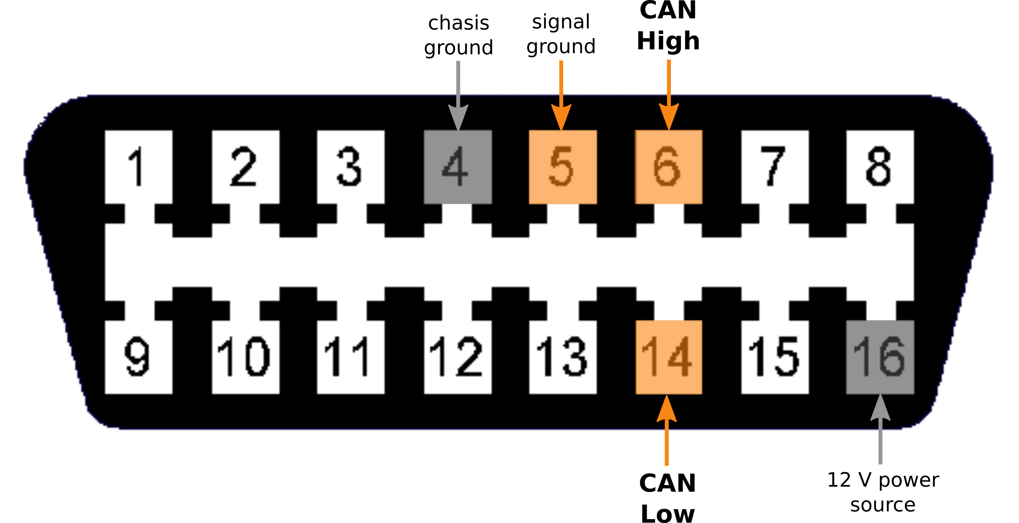


 Image 8: DEWE-43 is small and versatile device with 2 CAN portspacked together with 8 analog and 8 counter inputs


 Image 16: Change the Operation mode from Real measurement to Offline mode
 Image 17: Add a Test CAN (replay mode) as a device
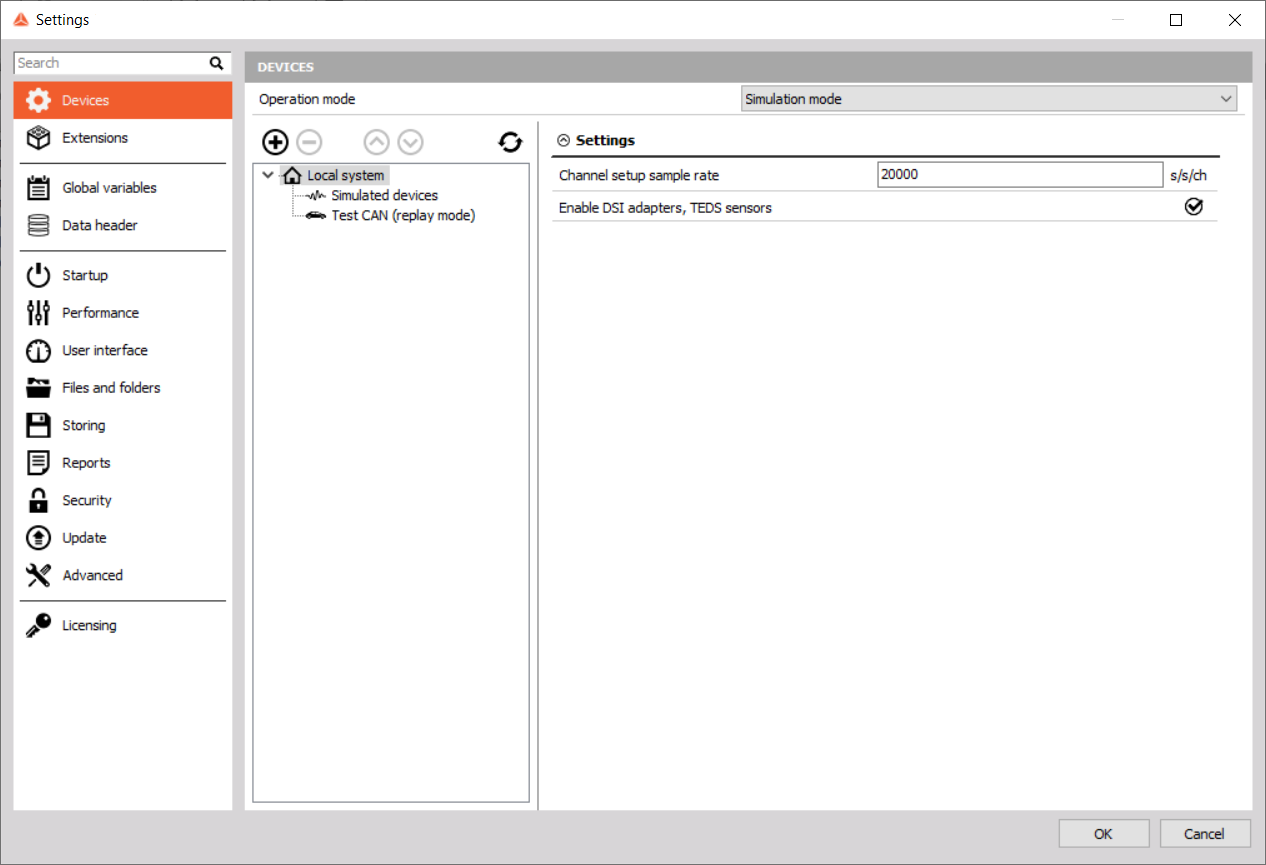 Image 18: Virtual CAN device settings


 Image 23: Acquisition update rate setup
















 Image 84: Steering wheel CAN message is now shown on the top of the message list as it is the most active