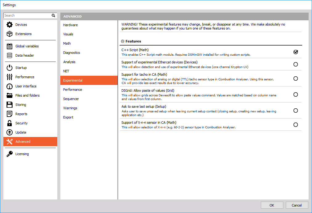
To create a new C++ Script we click the Math button and Add Math button which appears underneath it. In the menu that just opened up, we find the section called Formula and scripting and finally click on C++ Script.
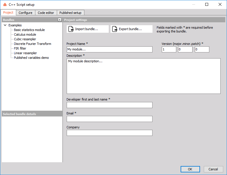
A new C++ Script setup window will appear as it is shown on the image 8. The setup window has four tabs: Project tab, Configure tab, Code editor tab, and Published setup tab. Our example will be split into steps, corresponding to these tabs.
 Image 8: C++ Script setup window
Published setup
But before we get started, let's click on the Published setup tab. We can see that a user interface not too dissimilar to other Math modules found in Dewesoft was automatically created; it has a section for input channels, empty space for output channels below that, as well as a section for defining and changing settings of our module. Since our module is currently empty, the form is also empty.
Project
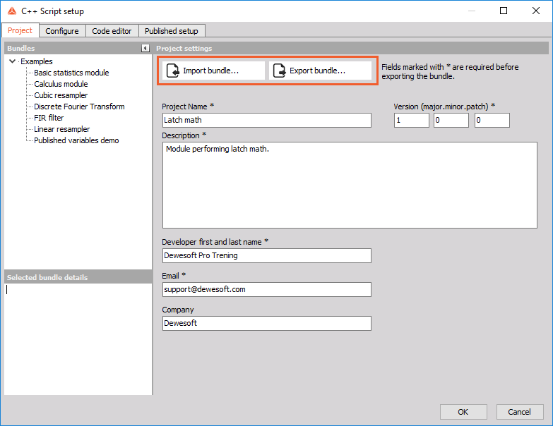
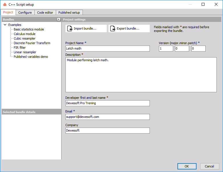
In the Project tab, we are going to specify the module name, a brief description of what our module does, and the version of our module. We proceed by filling out the Project name field with Latch math, Description with Module performing latch math and leave the Version fields as they are. Also fill out the Developer first and last name, Email, and Company text fields with your information.
Image 9: Edit the Project tab of C++ Script
When we are done, click the Configure tab at the top of the setup window.
Configure
After clicking on the Configure tab the first thing we get to change is the general behavior of our module. We can choose the calculation call and define the block size for our calculations. C++ Script can work in two modes: Sample-based, where each new sample in the input channels triggers the calculation step, or Block based, where Dewesoft waits for Block size new samples from input channels before calling our module. For our latch module example, we do not change the setting, because we want our calculation to be performed for every new sample of the signal.
Let's say we want the user of our module to be able to specify 2 settings: whether he wants to latch the output on a rising or falling edge (i.e. when the car is accelerating or decelerating), and the Criteria limit to determine which value the criteria channel needs to pass before we output the value (i.e. the speed of the car we are interested in). Configure tab is exactly the place where we can define user settings like that.
Published variables
Inside the Configure tab under Published variables, we can define various types of variables. The main idea behind defining the variables here instead of directly in our C++ code is that these variables are accessible from the Published setup tab and changing their values there does not require recompiling the code.
Under the Published variables tab click thebutton. This brings up a Variable setup form for defining our variables.
For start let's create a variable for deciding whether the latch condition is rising edge or falling edge on the signal. We do this by first filling out the Variable name section of the setup. We define the C++ variable name as "edgeType" -- this represents the name of the variable as it will later appear in the C++ code. We also define the Published name as "Type of edge", and this represents the name of the variable as it will appear in the Published setup tab.
Every time we fill in a field labeled "C++ X'', we are setting the X inside the C++ code, and every time we fill in a "Published Y'' field, we are changing Y in Published setup tab. Because "C++ X" fields need to be valid C++ variable names, we are not allowed to use spaces and special characters (other than "_") or start the name with a number.
Now we move on to the Variable type section of the setup window. Here we choose the Variable type as "Enumeration" from a drop-down list. After choosing "Enumeration" as our variable type a new section will appear where we input the values user can choose from; in our case we create two values "risingEdge" and "fallingEdge". To add a new value we simply click on the button. Now we can also define the Default value of our variable by choosing a value from the drop-down list. Lastly we can add a Published description for our variable. After filling out the Variable setup window click the Apply button.
Image 10: Setup the variable with rising and falling edge
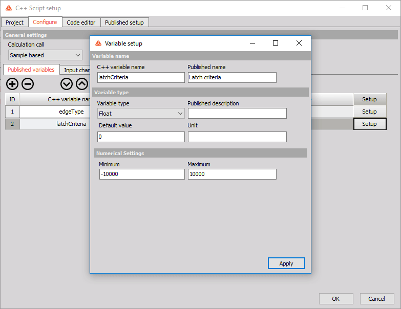
We also create another variable that our users will be able to change to control the value of the latch criteria. This variable will be of the type float and after choosing this type a Numerical Settings section appears, where we define the minimum and maximum numerical value user will be able to input for this variable in the Published setup tab.
Image 11: Define minimum and maximum numerical value
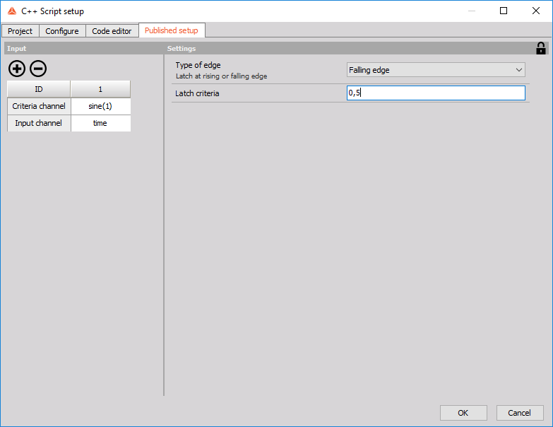
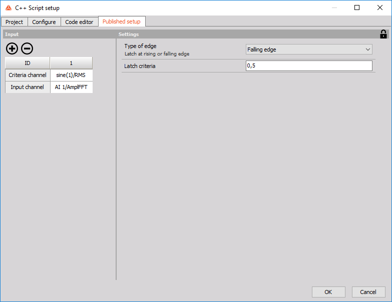
The two published variables we created above can now be seen in the Published setup tab of the C++ Script setup window. As we can see from the picture below, C++ Script automatically created a drop-down combo box for letting the user choose the type of edge, as well as an edit field through which the user can set the value of the latch criteria.
Image 12: Two published variables are now seen in the Published setup tab
 Image 1: Principle of C++ script
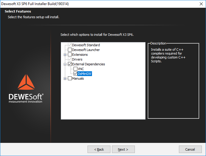


 button. This brings up a Variable setup form for defining our variables.
 button. Now we can also define the Default value of our variable by choosing a value from the drop-down list. Lastly we can add a Published description for our variable. After filling out the Variable setup window click the Apply button.

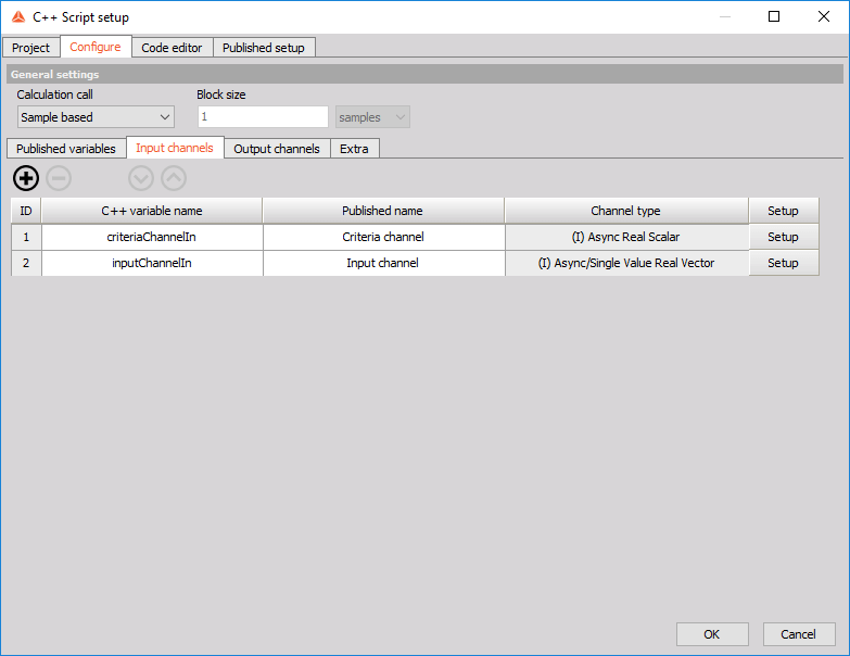
 button. This brings up a Variable setup form for configuring your input channel. Change the C++ variable name to "criteriaChannelIn" and Published name to "Criteria channel". Leave Value type as Scalar and Real, and tick the Synchronous check-box under Time base. Don't worry if you don't understand these settings yet as we will explain the different types of channels later on in this training. Clicking Apply you should find that the table now has a single row, containing "criteriaChannelIn" under the C++ variable name column and "(I) Sync Real Scalar" under Channel type.
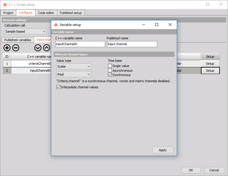
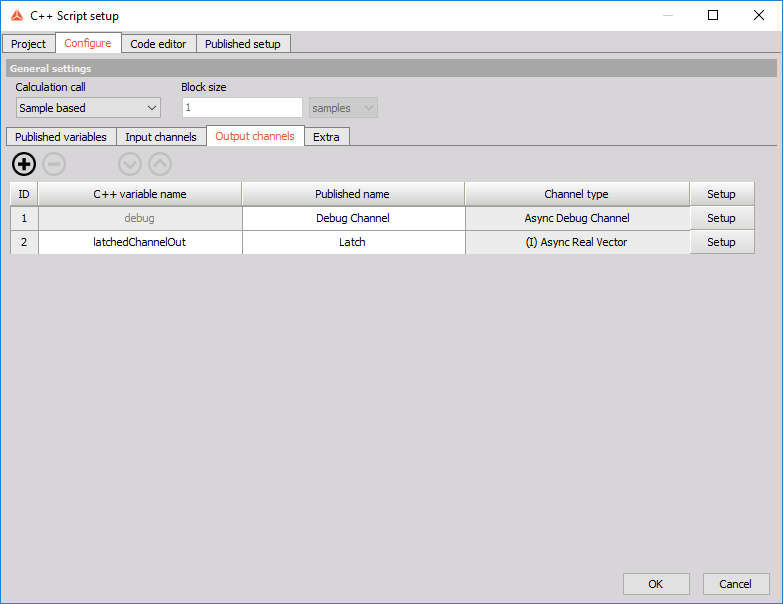
 button again. This brings up a form with settings slightly resembling the settings for input channels. Change the C++ variable name to "latchedChannelOut" and Published name to "Latch". Leave the Value type as Scalar and Real, change Time base to Asynchronous and leave the Expected async rate per second as 10. Don't worry too much about the meaning of Expected async rate per second setting either as it too will be explained in detail later on in the training. Clicking Apply creates a new row in the table with the channel we just made.

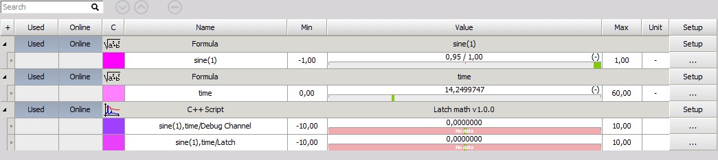
 button. From the drop-down list choose the "sine(1)" channel, and repeat the same process for Input channel only this time choose the "time" channel from the drop-down list.