In the Real measurement mode, we can see all the devices that are connected to our system.
All Dewesoft devices (SIRIUS, DEWE-43, KRYPTON, SBOX, ECAT-SYNC JUNCTION) are automatically recognized, but there are some devices, that can't be connected automatically.
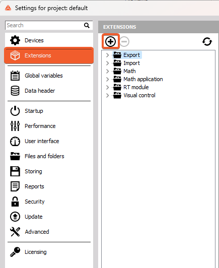
 Image 4: Dewesoft settings
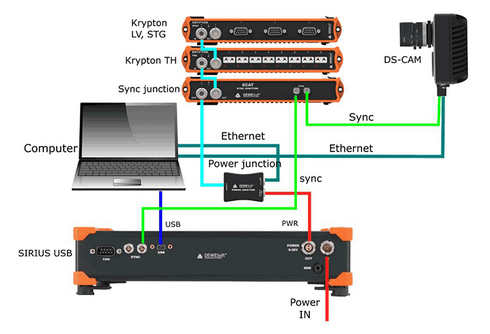
On the left side of the window, the structure of the system is shown. On the SBOX system, we connected USB devices (SIRIUS, DEWE-43) and EtherCAT devices (KRYPTON, ECAT-SYNC JUNCTION).
Image 5: Dewesoft settings Sbox system
With the plus button, we add devices that are not recognized automatically and with the minus button, we can remove them.
Image 6: Dewesoft settings add device When adding a new device, we can select many different devices (Camera, Automotive bus, Dewesoft NET...).
Image 7: Adding devices
If we have multiple slices, we can rearrange their sort order with the up and down buttons.
Image 8: Changing order of the devices
With the refresh button, we scan the whole structure of a system again.
Image 9: Refreshing device list
On the right side of the window, the properties of devices are shown and some settings can also be changed.
SBOX system
We can see the devices information (serial number, hardware, and firmware version).
Image 10: Sbox system information
If the S-BOX system is used, the remote mode can be used to turn the SBOX on or off from the remote distance.
Image 11: Sbox remote mode settings
The connector for power supply on SBOX has three pins, one is for voltage, one for a ground connection and one is a remote signal.
Image 12: Sbox power supply connector pinout
- Disabled: if the remote mode is disabled, SBOX can only be turned on or off by pressing the power button on the device.
- Remote power ON on external pin: The SBOX can be remotely turned on. When the voltage signal comes to pin for remote, the SBOX is turned on.
- Remote power ON and OFF on external pin: The SBOX can be remotely turned on or off. If the SBOX is off and the signal comes, it will be turned on. If the SBOX is on and the signal comes, it will be turned off.
In this case, we have connected multiple Dewesoft DAQ devices. If we select the DAQ device and click on it, we see the devices information (device number, serial number, hardware, and firmware version, temperature).
Image 13: Sirius system information
Bridge amplifier offset shows us the initial amplifier offset. Sirius connects the input short on and the offset is measured.
Image 14: Sirius bridge amplifier offset
With the button Reset offsets, we clear the initial amplifier bridge offsets.
Image 15: Cleared Sirius bridge adapter offset
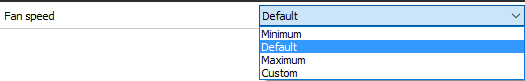
Fan speed can be set only to Sirius devices. We can choose from default, minimum or maximum. The custom speed is defined with the percentage of the maximum fan speed.
Image 16: Sirius fan speed settings
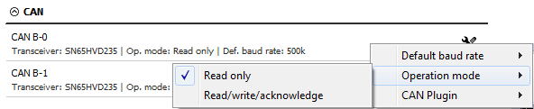
We can change the CAN baud rate and CAN operation mode (Read only or Read/Write/Acknowledge).
Image 17: CAN operation mode
Watchdog timer
Dewesoft X is quite often used in a much critical application where the control system depends on the data acquisition system or the data acquisition system outputs alarms used to warn the user or switch off the test. In such cases, it is important to know the operation state of the data acquisition system. Watchdog is a safety feature to switch on the digital output when the system is in operation and switches off if the data acquisition system becomes unresponsive. A timeout can be set to delay switching of the watchdog. This feature can be used with any Sirius slice having Digital output. For SIRIUS 8xSTGM DB special watchdog hardware (DS-WDT) is available which has four relay outputs for directly switching on and off. Relays can be programmed as the watchdog or standard alarm/manual outputs.
The Watchdog functionality enables an external way to monitor the behavior of the Dewesoft X software. To be able to use the watchdog a Sirius slice with a Digital out is needed or when using a single slice, the Sync signals can also be used. The slice must be connected in order to set up the watchdog.
Image 18: Dewesoft watchdog timer
Once enabled, the output selection can be made. Default settings are:
- Digital output: Ctrl DO Clk
- Timeout: 2 sec
- Operation mode: Active in measure mode
Digital output menu selects on which digital output the watchdog functionality is enabled. When using the Watchdog module, which is connected to the Sirius slice via a 25 pin cable, this selector should be set to Ctrl DO 1.
The watchdog can be only mapped to one digital output!
The timeout value specifies the time in which the Dewesoft must reset the watchdog.
Operation mode can be selected from:
- Always active in measure mode - watchdog functionality is active while Dewesoft X is in measure mode
- Active in setup and measure mode - watchdog functionality is active while Dewesoft X is in channel setup and while in measure mode.
- Always active - watchdog is always active.
Image 19: Watchdog timer operation mode
Digital output menu selects on which digital output the watchdog functionality is enabled. When using the Watchdog module, which is connected to the Sirius slice via a 25 pin cable, this selector should be set to Ctrl DO 1. The watchdog can be only mapped to one digital output!
The watchdog is not active while in Analysis mode!
The watchdog behavior is as follows:
- When the slice is powered up, the module is in the Alarm state (Watchdog LED is RED). The slice does not retain any information about watchdog after power loss!
- When Dewesoft X is started and no watchdog functionality was set for the slice in a previous session the LED light is RED
- When the watchdog functionality is set, the following occurs:
- Active in Ch. Setup is not set: The watchdog LED light is RED until the user switches to Measure mode; then the watchdog LED is GREEN. When switching back to channel setup mode the LED turns back to RED.
- Active in Ch. Setup is set: The watchdog LED light is GREEN in both Channel setup and in Measure mode.
- When disconnecting the slice from USB or turning off Dewesoft X software the watchdog will trigger (after the preset time in case of disconnect or computer/software freeze or immediately when exiting Dewesoft). The LED light will turn RED
The watchdog module itself has 3 additional outputs that are user-controlled via the A/D module. The respective A/D outputs are CTRL DO 2, CTRL DO 3 and CTRL DO 4.
All four outputs are relay-based with a possibility to connect with a NO (Normally open) or NC (Normally closed) position.
When the watchdog has triggered or upon power up the watchdog relay is not energized meaning that the NO position is OPEN and the NC position is SHORTED.
In DEWE-43 settings, we can change the CAN baud rate and CAN operation mode (Read only or Read/Write/Acknowledge). We can also see its name of the device, serial number, hardware version, and firmware version.
Image 20: DEWE-43
ECAT-SYNC-JUNCTION works in the same way as other Dewesoft USB devices. It is automatically recognized within Dewesoft X software. By default, ECAT-SYNC-JUNCTION will be set up to synchronize KRYPTON EtherCAT® and SIRIUS USB. The serial number and the firmware version can be seen and also updated.
Image 21: Sync junction system information
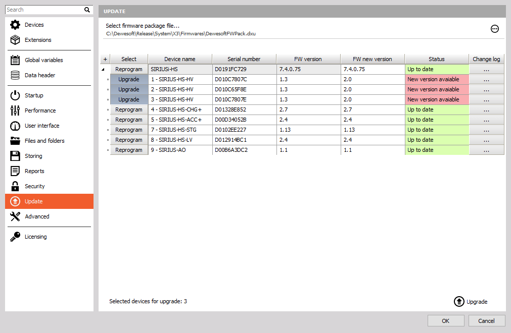
Under the KRYPTON section, serial number, hardware, and firmware versions are seen. Also, the firmware upgrade can be done.
Image 22: Krypton system information
Channel setup sample rate
Channel setup sample rate defines the sample rate of channel setup. Channel setup sample rate does not run with the full acquisition sample rate but with the reduced one.
Image 23: Dewesoft channel setup sample rate
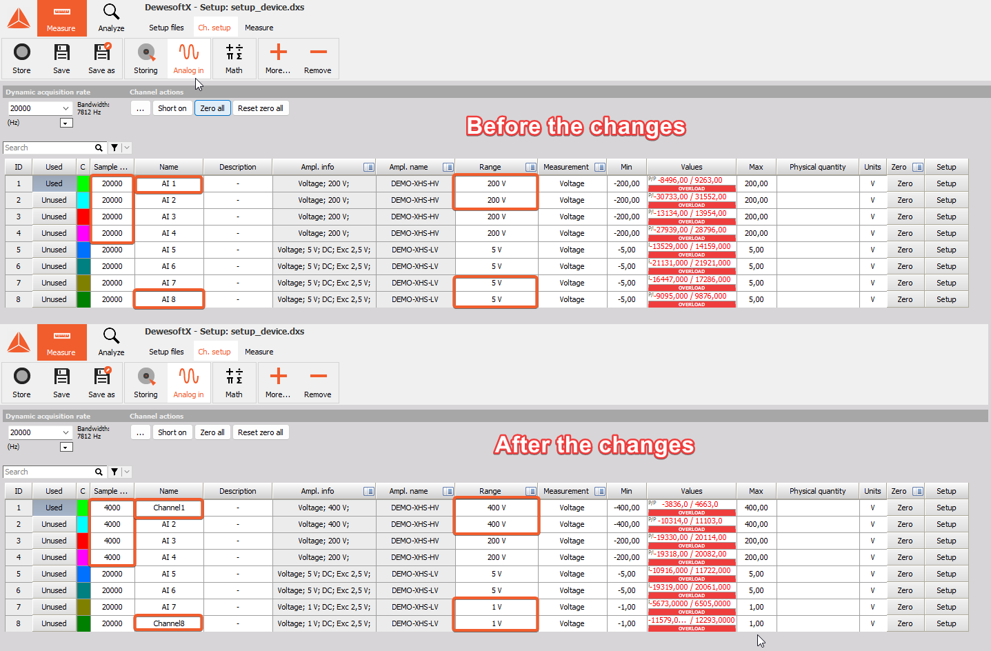
Let's take a look at a signal from a function generator (simple sine wave with 100 Hz). First, we let the channel setup sample rate at the default value, 20.000 s/s/ch.
When we enter the setup of the selected channel, we see the preview of the scope nicely.
Image 24: Scope preview 20ks/s/ch
Then we change the channel setup sample rate to 10 s/s/ch.
Now, the preview of the channel does not show the proper form of the signal, because it is sampled with a lower frequency than it should be.
Image 25: Scope preview 10s/s/ch
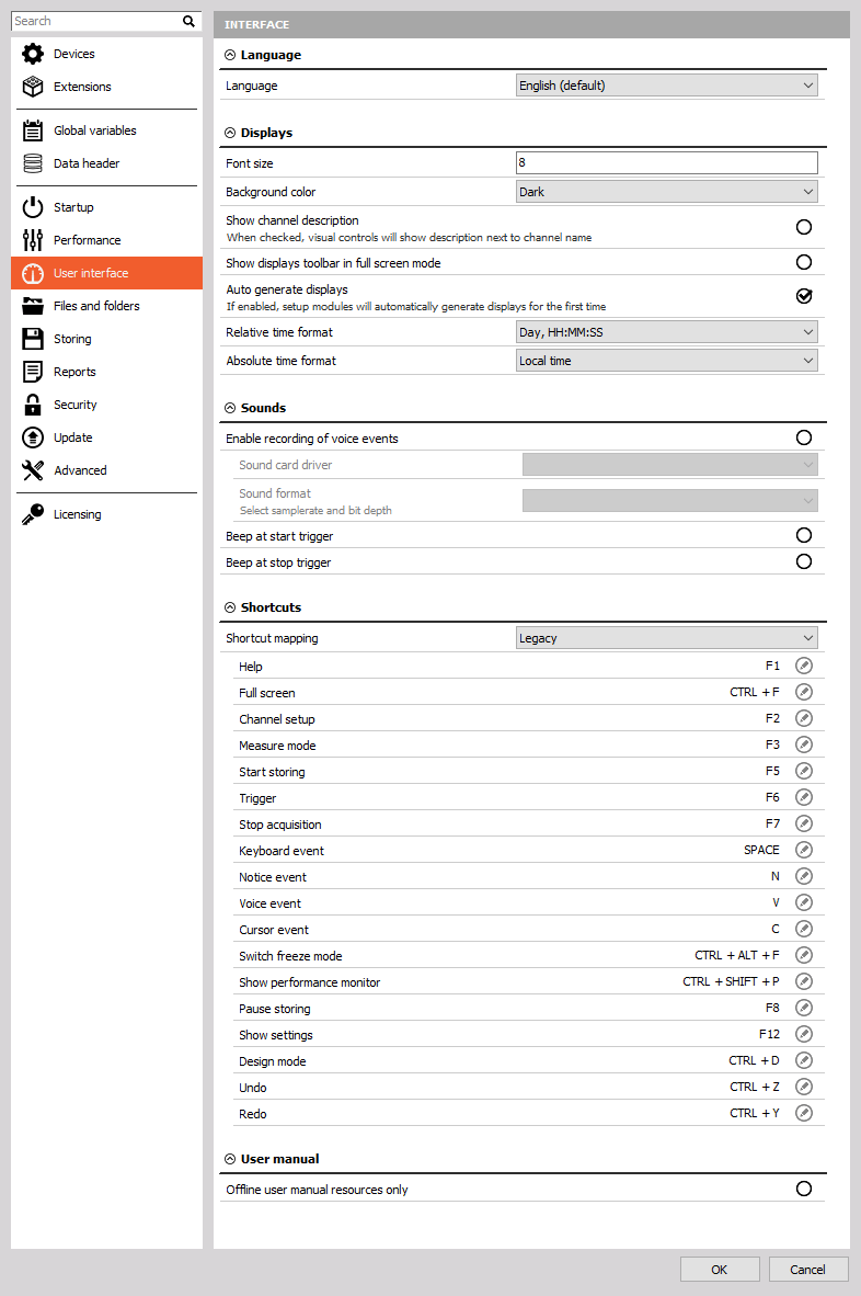
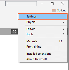 Image 1: Entering settings button
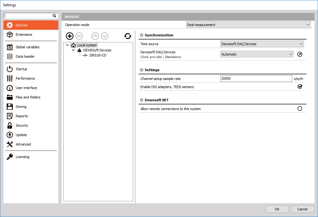 Image 2: Dewesoft settings structure
  Image 3: Dewesoft settings operation mode