Data Storing and Triggering Options

Storing strategies are very important for the entire System. That's why Dewesoft offers many ways of how to store data. Learn how to store data, which are the possible storing options, how to set up trigger conditions, what is data manager and how to use it and more.

Storing strategies are very important for the entire system. That's why Dewesoft X offers many ways of how to store data.

You can see all the storing options in Measure mode under the Storing tab.

storing options in Dewesoft
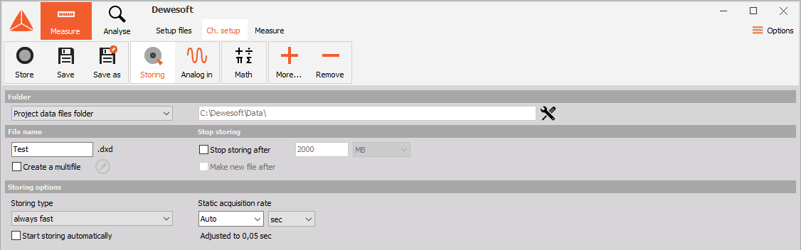
Image 1: Storing options 

These are the possible storing options in Dewesoft X

  • Always fast
  • Always slow
  • Fast on trigger
  • Fast on trigger, slow otherwise.

With always fast and always slow storing options you can choose between different static acquisition rates and units.

When you select one of the triggers storing options Trigger setup tab will automatically appear on Dewesoft X Setup screen.

NOTE: With Dewesoft X, you can trigger from your signals by setting any channel(s) to start and stop recording according to levels.

Before we explain other functions on the screen above, let's first take a look at how to name and save files that will be stored.

We can change the folder where data is stored under the Folder section. 

folder for the datafilesImage 2: Data files folder


Project data files folderFolder from project settings
Custom folderArbitrarily chosen folder from local storage

We can define the file name for each measurement separately by entering it into the edit-field
file name field
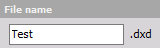
Image 3: File name field

For repetitive measurements, we use the Create a multifile function.

storing multifile
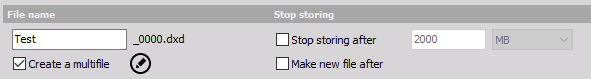
Image 4: Create a multifile 

Multifile automatically assigns a new file name for each cycle (start) of storage. File names can be either consecutive (such as 0001, 0002, 0003) or by the date and time.

multifile filename setup 
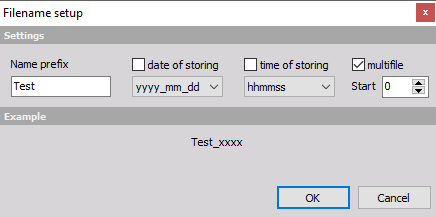
Image 5: Multifile name by the date and time


Additionally, you can define how a new file will be created by selecting Make a new file after checkbox. The criteria for switching to a new file are either the file size or time interval, which can be defined in seconds, minutes, or hours.

MBCreates new file after defined file size in Megabytes is reached
hCreates new file after defined time in hours is reached
minCreates new file after defined time in minutes is reached
secCreates new file after defined time in seconds is reached
triggersCreates new file after the trigger occurs

This can be very useful when acquiring data for longer time periods. If we choose to switch the file each hour with absolute time, then the switching will be done exactly on the hour (01:00, 02:00, 03:00...). The time will be taken from absolute PC time (or another more exact timing source, if available, as defined in the hardware setup). The file switching is done in such a way that no data point is lost in the process.


First, let's look at how to store full speed data in Dewesoft X. Let's perform a short measurement with Sirius unit and tuning forks and explain the use of basic buttons.

Let's first look at the Keyboard Shortcuts that can be useful when working with Dewesoft X.
F2 - go to Channel Setup
F3 - go to Measure
F5 - Store (if you are using a later version than SP5 you can stop storing without stopping the Acquisition)
F7 - Stop storing

In Measure - storing there are three useful Keyboard Shortcurs
Space - Keyboard event
n - text (note) event
v - voice event

First, we will learn how to store data in Dewesoft X.

Let's perform a short measurement with Sirius unit and tuning forks and explain the use of basic buttons.

If we want to store measured data, we need to be in Measure mode, where we can see Store button.


measure mode Image 6: Measure mode in Dewesoft


For start storing, we need to click Store buttonstore button

 on the main menu.

Once we do that, a small Warning window will appear if the file which we want to write to already exist on the hard drive.

We can either overwrite the previous file or use another file name.

warning before the new filenameImage 7: Warning


Now the data will be stored to the file with full speed.

NOTE: Data are stored with the speed that is defined by typing in the Sample rate. That speed can be different from channel to channel by setting up the Sample rate divider.

recorder measurementImage 8: AI data file on the Recorder


When we start storing, these are the actions that we can select between different storing options.

The Store button changes to

store button

and if we click the Pause button,


pause buttondata will still be acquired, but storing will be paused. At that point, the Pause button caption changes to Resume button 

resume button

Store button stays the same 

store button
 
and if we click Store button again, storing will be resumed. Due to this, there will be two sections of data visible in Analyse mode.

recorder multifile overviewImage 9: Paused and countined measurement shown on the recorder


We can also Stop and freeze the storing.

Note: All the action buttons need to be clicked manually and if we are in Measure mode data isn't yet stored. For that, we need to use Store button.


If we don't make any changes in Storing settings and go directly to Measure marker, the data will be stored all the time with the selected Dynamic acquisition rate. Now the data will be stored to the file with full speed.

The procedure of how to store data is the same as we mentioned it in the beginning.

To start storing, click Store 


command buttons for storingImage 10: Control buttons


in the main menu.

Now the data will be stored to the file with full speed.

The Store button changes to 

store button

 and if we click the Pause button 

pause buttondata will still be acquired, but storing will be paused. At that point, the Pause button caption changes to Resume button

resume buttonStore button stays the same

store button

and if we click it again, storing will be resumed. Due to this, there will be two sections of data.


datafile of the two section dataImage 11: Two-section data


If the user clicks Analysis, he will see two sections with data and space in between will be blank - no data is stored there 


datafile with free space betweenImage 12: Two-section data with the blank space between


This function stores data at intervals, set with Static/reduced rate. Even thought storing is set to slow, Dewesoft X will acquire the data with full speed, calculate the minimum, maximum, average and RMS for this time interval and store only these values.

If we look at the example below the static acquisition rate is set to 0,1 second which means, that in this case we will use much less disk space for storing our data.


always fast storingImage 13: Static acquisition rate


If our data consists of events which can be captured, we can choose to store with two options of triggers. The trigger event can be defined in the software and then Dewesoft X will wait for this event and store only the portion of interest.

If the Start storing automatically is selected, the data storage will be automatically started as soon as you change to any online display (scope, recorder,... ).

If you want to stop storing, just press the Stop button or F7 on the keyboard. This function is independent of the storing type (fast, reduced, triggered,...). This function can be used together with the auto load function of Dewesoft X for highest automation.

If we want to acquire the data with slow speed, we can choose the always slow storing option.

The data will be stored at intervals, which are set with static/reduced rate.

In our case, this is set to 0,1 seconds. That's why much less disk space will be used for storage. Even though storage is set to slow, Dewesoft X will still acquire the data at full speed, calculate the minimum, maximum, average and RMS for this time interval and store only those values.

Let's store some data and take a look how the data appears in the recorder. This is what the data looks like at full rate in Measure mode.

data at full rate in Measure modeImage 14: Full rate data in Measure mode


And now let's switch to Analyse mode. The data will be shown as the envelope of the original signal since the full rate is no longer available, merely the 0,1-second values. We can also switch to average or RMS modes in the recorder setup to see those two parameters.

data shown as an envelope Image 15: Measured data in Analyse mode


The recorder below shows the RMS of the signal. We can judge from the average, RMS and min/max values what the original signal could be. For example, if there is a big maximum and the average value did not grow, we can deduce that there was a short spike in that channel.

spikes in dataImage 16: RMS of the signal


If Fast on trigger is chosen, data will be stored with the dynamic rate once the trigger point occurs.

If our data consists of events that can be captured, we can choose to store it as fast on the trigger. The trigger event can be defined in the software and then Dewesoft X will wait for this event and store only the portion of interest. This can be set by choosing the fast on trigger storing option. After doing this, the new tab Trigger will appear where we are able to set up the trigger condition and strategy.

First, we can choose to define the pre-time, post-time and holdoff-time.

trigger setup settingsImage 17: Fast on trigger settings


PRE TIME is the time which will be stored before the trigger event occurs.
We define the 100 ms before an event as the pre trigger. This means that Dewesoft X will keep the data in the buffer until the trigger event occurs and then store this data to the file before the trigger in addition to the data after the trigger occur.

POST TIME is the time after trigger event which will be stored.
If this is not defined, Dewesoft X will continue to store until we stop it manually or a stop condition occurs.

HOLDOFF TIME is the time which is between the last trigger and next one.

For this example, we want to capture trigger shots, so the post trigger should be set to 200 ms, so a total of 300 ms of data will be captured per trigger event. Now we need to define the trigger conditions for the beginning of storage. Let's add one trigger condition by clicking setup to define it.

storing settingsImage 18: Start storing conditions


In the Trigger setup window, we can choose Channels for triggering. We can select several channels for triggering, but since this example deals only with one, there is only one choice.

Then the trigger criteria need to be defined. The user can trigger on time data, time or FFT.


condition setup with simple edge and positive trigger level

Image 19: Condition setup

Time triggering includes edge, filtered edge, window, pulse-width... on real data, average or RMS values.

trigger on simple edge modeImage 20: Trigger on modes

For this simple application, only the simple edge with a trigger level of 0.5 will be selected. This means that when the value crosses the 0,5 V limit, it will produce a trigger. One can already test the behaviour of the trigger from the scope in the lower left side of the setup window.

trigger on simple edge mode Image 21: Trigger on positive simple edge


Now let's take some measurements. The user just needs to meet the trigger criteria with sensor to produce the necessary trigger. We can see from the recorder that the first shot was not high enough, therefore we hit it harder. That did it, and one we can see the beginning of the storage event, the trigger event and the end the of storage event.

Note that the Store button changed the name to Arm 

arm button

 and there is an additional Trig button

trigger button 

This is the manual trigger to issue a to trigger even without an event.

Let's review the data being stored. We can see that only the trigger events are stored, yet for the rest of time the data is blank. Note that there is a new button, called TRIGGER MODE, in the data preview. This gives us a chance to review the trigger events without zooming in on the data. If it is clicked, the first trigger event is automatically zoomed in.

The trigger mode button changes to an "arrows" button, where we can browse between the events. If those two buttons are clicked, the recorder shows the trigger events one by one. On the data preview, we can see the currently selected trigger event. Right, click on the recorder to zoom out to the full region and to leave trigger mode.

Note that there was one peak at the beginning of storage. It was not enough to be stored with the trigger, but sometimes it is still nice to see what the values in the regions without the trigger event were.


Data will be stored with the dynamic rate at trigger points, and with the reduced rate when there is no trigger.

fast on trigger slow otherwise optionImage 22: Fast on trigger, slow otherwise storing options


To be able to acquire data with two speeds, we need to use a different strategy: Fast on trigger, slow otherwise. All the settings for this mode are the same as for fast on trigger. It should be noted, however, that if the user acquires and reloads similar data with this strategy, the data is also reduced for the regions without the trigger event. This can be seen on the picture below.

fast on trigger slow otherwise option datafileImage 23: Data sections with different speeds


By zooming in on the data, one can see the reduced, stored data before the trigger, where only the maximum and minimum of the signals is seen and then for a region with trigger the full speed data can be seen.

fast on trigger slow otherwise datafile Image 24: Zoomed region with different speed


When the static mode is selected, the system will still run at the dynamic sample rate shown in the box DYNAMIC ACQUISITION RATE, however, it will not store every data point. Instead, the system will reduce the data continuously according to the static/reduced rate selected here.

static acquisition ratesImage 25: Static acquisition rate


You can select the value from the drop-down list, like 0.1 seconds. This means that every 0.1 seconds the reduced data will be available.


If you select AUTO, the static/reduced rate will be adapted automatically depending on the setting of the dynamic acquisition rate.


You are also allowed to enter your own values, but be aware that not all values will be accepted - if so the real value will be mentioned below the drop down list.


For example, if we have a dynamic rate of 1000 Hz, and a static rate of 5 seconds, and we check that we wish to store the static rate, the system will sample at 1000 Hz, but will store a set of min/max/ave/RMS values for each input every five seconds.


This means that 5000 samples are going by for each channel, every five seconds. Are they ignored? No - they are used to derive the min/max/ave/RMS values which are saved for each active input, at the static rate!
So, each set of reduced samples are based on all 5000 samples that were seen for each channel between static intervals.

Important: when the system does this, it does not make a single column of data for each channel - instead, it creates multiple columns of useful data for each channel, including the min/max, RMS, and average values that were seen between each interval of the static/reduced rate.

CHANGE STATIC/REDUCED RATE SCALING

Sometimes it is required to change the units for the stating / reduced rate (Hz, sec, min, samples).

adjusted static acquisition rates Image 26: Adjusted static acquisition rate


Simply click on the small arrow below the drop-down list to select another scaling.


For each unit (scaling) Dewesoft X will adapt AUTO value automatically (and show in Adjusted to field), depending on the setting of the dynamic acquisition rate.


On this screen start and stop trigger conditions can be set:

- Trigger setup to set the storage time before and after the trigger event
- Start trigger setup defines start and stop trigger condition; with Don't store setup
- Stop trigger setup defines when the storage should be stopped

TRIGGER SETUP

The Trigger setup can be used to influence the storage before and after the trigger event. Four settings can be used to achieve the desired result:

trigger setup Image 27: Trigger setup


PRE timePre-trigger time, defined in milliseconds. This value defines the storage duration before the
trigger event occurs Dewesoft X will keep the data in the buffer until the trigger event occurs and then store also this data to the file.
As a standard, this feature is not selected and the storage starts with the trigger event itself.

POST time

Post trigger time, defined in milliseconds. This value defines the storage duration after the
trigger event has been finished Dewesoft X will continue to store until we stop it manually
or stop condition occurs.
As a standard, this feature is not selected and the storage stops immediately after the trigger event is
over.
HOLDOFF timeGives you the possibility to suppress trigger events for a certain time after the last event had
happened. This feature is not selected as a standard and will normally used when you have
plenty of events or very long storage times.
Post time extensionThe posting time extension is checked automatically as long as the Post time is not selected.
The acquisition duration will be prolonged when further trigger events appear while the first
one is still recorded.


The following example is set to 0,1 sec Pre and 0,2 sec Post time, so we will capture 300 ms of data in total per trigger event:

trigger setup with the pre timeImage 28: Pre time and post time


START TRIGGER SETUP

When you select the trigger setup for the first time, there is no start trigger condition defined:

start trigger setup, start storing conditionsImage 29: Start storing conditions window


When you press:

+ (Add button)A new trigger condition will appear immediately in the list
- (Remove button)The selected trigger condition is removed from a list
Use the Add button to add a new Start trigger condition:
simple edge start storing conditionImage 30: Simple edge start storing condition for the first AI channel


After pressing Add button beside this new trigger Start storing conditions also appear:

- empty Don't store conditions section on Start trigger setup part of the screen
- empty Stop trigger conditions in new Stop trigger setup column


As a standard, the trigger condition is set to a Simple edge trigger with a positive edge at the first active analog input channel.


When we select the Setup button on the trigger condition line of Dewesoft X Setup screen, the Condition setup window appears to enter the trigger condition settings.

''DON'T STORE'' SETUP

The Don't store trigger condition and Setup works in exactly the same way than the Start trigger setup.
This function can be used to suppress data storage for the defined condition.


For example, a machine is producing a certain part and you measure the pressure. The system should trigger when the pressure grows above a certain limit. But you only want to store the data if there is really a part in the machine. Then you can connect a signal to another channel which reports if the unit is present or not and use this result as a Don't store function

STOP TRIGGER SETUP

The Stop trigger condition and Setup works in exactly the same way than the Start trigger setup (see above). The only difference is that this section defines when the storage should be stopped.
Use the Post time feature from the Timing setup to prolong the storage time if required.

REMOVE A TRIGGER CONDITION

To remove a trigger condition simply click on the trigger illustration or the description field to select the condition, the selected field becomes darker - and press the minus button.

remove the start storing conditionImage 31: How to delete the start storing condition


TRIGGER CONTROL ELEMENTS
To activate the selected trigger condition, just switch into an online
display (scope, recorder,...) and press the Arm button on main
Dewesoft X tool bar or F5 on the keyboard. As soon as the trigger
the condition appears on the input, the data will be stored into a file.
control elements buttons

When the trigger condition is activated, we see additional 

trigger button

Trig button, which tells us that we are using triggered storing. We can also press this button to issue a manual trigger.

If you want to force a trigger event even when it isn't available, press the Trig button or F6 on the keyboard. Trigger shots will appear in the scope and the Trig button flashes.
If several trigger events appear, all of them will be stored in the same file. Dewesoft X offers a special analysis feature in the Analyse mode for easy data analysis.


Dewesoft X offers several different trigger conditions, which can be set in Condition setup window. Trigger conditions can be combined completely independently, that combined with an OR function. That means any defined trigger condition has to become true to activate the trigger.

When we select the Setup button on the Dewesoft X Setup screen - trigger condition line, the following Condition setup window appears:

condition setup Image 32: Trigger level


In Condition setup window we can enter all the trigger condition settings. The Source section contains a channel list in two different tabs. All chs tab represents all used channels and AI tab filter only analog input channels. In lower part the current signal value is displayed. The white vertical lines displayed indicate when the trigger condition became true. On screen right side the Trigger on section represents trigger settings. This fields depends from selected trigger type, below trigger settings symbolic trigger curve is displayed. 

Choose the trigger condition according to your requirements and press the OK button to accept the trigger settings.

TRIGGER TYPE

The following trigger types are supported:

  • Data
  • Time
  • FFT


1. Define the Value
When the data trigger is selected, you can also choose between Real data,
Average or RMS from the drop down list for your trigger condition.
condition setup trigger data value
2. Define the Mode
Select the trigger type Simple edge, Filtered edge, Window, Pulse-Width, Window and pulse-width or Slope from the drop down list.
condition setup trigger data mode
3. Set up other trigger condition
These settings (e.g. Slope, Trigger level, Rearm level, Pulse time...) depend on selected trigger type in Mode field.

TRIGGER MODE AND SETTINGS

SIMPLE EDGEPOSITIVE SLOPENEGATIVE SLOPE

This is the most used trigger condition with
data acquisition systems.
The trigger event is a rising or falling edge,
which crosses a defined level.

simple edge positive slope

Trigger on rising edge when signal rises over defined Trig level.

simple edge negative slope

Trigger on falling edge when signal drops bellow defined Trig level.

FILTERED EDGE

POSITIVE SLOPENEGATIVE SLOPE
is basically the same as the simple edge trigger, except for the rearming level.
This level can be used to define a second level, which must be crossed before the trigger condition can become true again.
This trigger type is mostly used with very noisy signals.

filtered edge positive slope

Trigger on rising edge when signal
rises over defined Trig level; retriggers only when Rearm
level has been crossed.

filtered edge negative slope

Trigger on falling edge when signal
drops bellow defined Trig level; retriggers only when Rearm
level has been crossed.

WINDOWENTERS RANGELEAVES RANGE
works with two independent levels, which build
some kind of window.
The trigger condition can become true when the signal enters or leaves the window.

window enter range

Trigger when the signal enters the window - signal falls below Upper level or rises above
Lower level.

window leaves range

Trigger when the signal leaves the window - signal rises above Upper level or falls belowLower level.

PULSE-WIDTHPOSITIVE PULSENEGATIVE PULSE
Longer than time
checks in addition to the level (like the simple edge trigger) the duration Time of the event and triggers only if the event is longer above the selected level

pulse width positive pulse

Trigger on rising edge when signal rises over defined Trig level and stays above this level longer than selected Time.

pulsewidth negative pulse longer than

Trigger on falling edge when signal drops bellow defined Trig level and stays bellow this level longer than selected Time.

Shorter than time
checks in addition to the level (like the simple edge trigger) the duration Time of the event and triggers only if the event is shorter above
the selected level

pulsewidth positive pulse shorter than

Trigger on rising edge when signal
rises over defined Trig level, but
falls below this level earlier than
selected Time.

pulsewidth negative pulse shorter than

Trigger on falling edge when signal drops bellow defined Trig level, but rises above this level earlier than selected Time.

WINDOW AND PULSE WIDTH
condition combines the features of the window and the pulse-width trigger; it is very powerful, but you really have to know what you expect to trigger on.

LEVEL IN RANGELEVEL OUT OF RANGE
Longer than time

window and pulsewidth in range longer than

Trigger when the signal enters the
window (signal falls below Upper level or rises above Lower level) and stays inside
for a longer than defined Time.

window and pulsewidth out of range longer than

Trigger when the signal leaves the
window (signal rises above Upper
level or falls below Lower level) and stays outside for a longer than defined Time.

Shorter than time

window and pulsewidth in range shorter than
Trigger when the signal enters thewindow (signal falls below Upper level or rises above Lower level) but leaves before the defined Time is over.

window and pulsewidth out of range shorter than
Trigger when the signal leaves thewindow (signal rises above Upper
level or falls below Lower level) but
returns before the defined Time is over.

SLOPEPOSITIVE SLOPENEGATIVE SLOPEANY SLOPE
Smoother than Delta time

slope positive slope smoother than

Triggers when signal rises over
defined Delta level later
than defined Delta time

negative slope smoother than

Triggers when signal drops
below defined Delta level
later than defined Delta time

any slope smoother than

Triggers when signal rises over
or drops bellow defined Delta
level later than defined Delta time

Steeper than Delta time

slope positive slope steeper than

Triggers when signal rises over
defined Delta level earlier
than defined Delta time.


negative slope steeper than

Triggers when signal drops
bellow defined Delta level
earlier than defined Delta
time.

any slope steeper than

Triggers when signal rises over
or drops bellow defined Delta
level earlier than defined
Delta time.

ABSOLUTE (TIME ONLY)

time absolute equal to

The system triggers exactly at the defined time hh:mm:ss.xxx (also every day if the time matches).

time absolute every

The system triggers every defined time x [unit], the time starts running from the beginning of measurement.

RELATIVE

time relative equal to

The system triggers when the defined time x [unit] has been passed since the measurement has been started.

time relative every minutes

The system triggers every time x [unit], the time starts running from the beginning of measurement.

Time format select from drop down list:

time format

Time select from drop down list:

time format every

[unit] select from drop down list:

time format every minute


Up to now, we triggered the system only on amplitude values over time and/or directly on time. The FFT trigger allows us to trigger amplitude values in the frequency domain.

This type of trigger is very helpful in any kind of dynamic applications where you want to supervise the frequency behavior of the system under test.

condition setup fftImage 33: Trigger setup on amplitude values of the frequency domain


FFT options

To trigger on frequency changes you have to define the FFT options to get a useable result to trigger on:
- Number of lines (256 to 64k),
- Window type (Rectangular, Hanning, Hamming, Flat Top, Triangle, Blackman and Exponent down) and
- Overlap (0, 25, 50, 66 and 75%)

Preview at the left bottom area shows the change effects on the FFT immediately. On this display can be select beside Logarithm (see the display below) also Linear display.

Condition setup fft log linImage 34: Changing between Logarithm or Linear display


Limit table

After you have done your FFT option settings you have to define:
- Number of points (limits on Limits table)
- the limits - Ampl. levels for f [Hz] on Limits table.

Default (standard) Number of points are 2. The standard Ampl. level is 1 for 0 and max. frequency. You can click on this field and change this value.

condition setup fft logImage 35: Limit table 


You can increase the Number of points to expand the table (e.g. 6 in the example below).

condition setup fft log tableImage 36: Expanded table to an arbitrarily curve


You can now define the limits in two ways:

1. Enter the values manually
When you enter the values manually into the table, you normally take just a viewpoints to define the frequency mask.

2. Take current measurement from the system
The second way is to take a frequency mask out of the currently displayed signal. To do that simply presses the Get current data button.
The currently calculated FFT will be stored as a mask and displayed both on the preview display and in the table at the left bottom.

Now you can manipulate the mask by editing the table or - much faster - pressing thebutton to move the limit up / down and the  button to add/remove limit in the frequency domain.

condition setup, get current dataImage 37: Get current data from the measured frequency values


Examples:

condition setup frequency limitsImage 38: Modified amplitude-frequency values. 


Data header allows us to define input fields in which operators can enter additional not measured parameters at start or end of the measurement.

data header settingsImage 39: Data header settings


Icon bar

Icon bar in Data header settingsImage 40: Icon bar

The icon bar at the top of the window allows you to change the right section of the window. We will now check icon by icon the functions. They can be used to create, delete, or move fields. The currently selected field will have an orange box around.

Info field

The Info button adds a new line in the right section of the window.

data header entriesImage 41: Adding info entry 


Just click in the new line and enter the desired text, for example, 'File header information'.

Image 42: You can rename the Info description


Input field

The Input field can be used for any single line values or comments (you can use it for example for location information...).

Let us create a new field with press the Input icon:

data header input fieldImage 43: Input field


and rename it (for example to 'Location'). To rename the field, just click on the name and overwrite it:

data header input field2Image 44: Rename the input field


Selection field

The Selection field can be used for creating the list of 'value' and is very useful when you have to use the same 'value' very often. This can be for example a list of user names or also a list of departments within your company.

Let us create a new list with press the Selection icon:

data header selectionImage 45: Adding the selection field


and label it (for example 'User' - click on 'Selection' and overwrite it):

data header selection fieldImage 46: You can rename the selection field


Now you have to define the content of your list. To do that, press the ... button on the right side and Create Selection List window appear.

Enter the desired names in the New Item field and press the Add item button:

data header create selection listImage 47: Creating the selection list


The name will appear in the list on the left side, in our example labeled User 1: 

data header create selection listImage 48: Adding the items to the selection list 


Enter as many names as required. You can also edit values directly in the list by selecting an item.

To remove an item, just select it from the list on the left side and press the Remove Item button. When all names are entered, press the OK button or press Cancel to reject all entries. The result of upper entries is the following drop-down list in the global header window :

data header user selectionImage 49: Selection dropdown menu


Position up/down

With both buttons up and down, you can now change the position of the:

- File name field
- Comments field
- Input field
- Selection field
- Info field (like created above)

You can change the position of fields at any time. Just select it (the red box will appear) and move it up or down using appropriate button.

For example, we want to move above created info field to the top of the window, press the Move up button twice:

data header different entriesImage 50: Data header entries


Delete field

To remove unused or non-required fields, select the field and press the Delete icon. The only field you can't delete is the File name entry field.

Ask for the header on the start option will pop up a window with all entries before the start of storing. Ask for the header on the end will open the same window when the measurement is stopped.

Data headed pop up window before storingImage 51: Pop up window before storing to entering the values 


The data manager is a new plugin for copying acquired data to FTP server or to Local folder.

This is Data manager's main functions:

- Copy files to network drives
- Copy files to FTP server
- Stop measurement / Shut down the PC
- Remove old files

You can download Data manager from Download section on our web page.

When we download it, we need to go to Dewesoft X.

First let's go to settings in the right upper corner of the screen and enter Settings.

This is the screen that opens. We need to go to Extensions marker and select New extension on a + button.

settings extensionsImage 52: How to add an extension


settings how to add data manager extensionImage 53: Adding the Data manager plugin


After we press OK, we can see, that Data manager was added to our Extensions list.

Our next step is go to Channel setup and enter the DataManager2 marker.

When we press the button, this is the screen that appears:

data manager extension overviewImage 54: Data manager plugin


Our screen is divided into three sections: Stop and Shutdown, Transfer files and remove files.

1. Stop and shut down

We can choose when we would like to stop storing or shut down the computer. We can do it after selected Async channel has no new data to store within specified timeout or after the file is transferred.

data manager stop and shutdownImage 55: Stop and shutdown section in the Data manager


If we choose the first option, then we need to select the Async channel option, timeout and action type.

2. Transfer files

data manager transfer filesImage 56: Transfer files section in the Data manager


We can transfer files to a specific location on a disk or to FTP server. We can decide either we would like to copy all files or every x-the file.

If we transfer files to a Disc location, we simply select the Directory where data will be copied. We can also see all the existing files.

If we decide to transfer data on an FTP server, we need to type in the specific information, like Host, Port, local folder, etc.

There are also some additional options. We can choose to rename the existing file, overwrite it, skip it or resume it. we can also decide to delete the files after transferring them and copy files which transfer wasn't successful. Some FTP servers demand passive connection, so It is always good to test the connection to make sure that it works properly.

3. Remove files

Our last field allows us to remove specific files.

We can select the number of days that need to pass before the files are removed from the local folder. Please don't skip the WARNING note. This option will remove all old files from the data folder.

data manager remove filesImage 57: Remove files in the Data manager 


The time at which Dewesoft X stores the files by default is always Coordinated universal time (UTC), but it can display stored data in local time, UTC time, and telemetry time.

The problem that can follow is that for example if the files were recorded in Russia at 10pm, it was stored in UK at 7pm (local time) which is exactly what is shown when you look at the file time in UK.

When your work with customers doing long-range rockets, it becomes even more complicated as the time zone changes during recording every x minutes. That's why in Dewesoft X you have the option to show the file time format in local time, UTC, and telemetry UTC (day of the year). 

storing time formatImage 58: Local time and UTC time settings