TEDS Sensors (IEEE 1451.4) and Sensor Database

TEDS is a set of electronic data that specifies the type of sensor, describes its interface, and gives technical informations (sensitivity, bridge type, excitation, ...).

Did you ever make the wrong measurements due to wrong sensor scaling? 

No?

Then you probably don't have many years of experience. Every experienced measurement engineer we know just smiles - a bit bitter though - when you ask him such question :)

There are several ways how the measurements can be messed up. Wrong sample rate, wrong amplifier range, sensor wiring are common errors. But when talking to the customers, entering wrong sensor scaling is one of the most common errors.

The idea of the Transducer Electronic Data Sheet (TEDS) is to eliminate this issue by equipping each sensor with a small chip that has the information about the sensor itself as well as how amplifiers must be set.

TEDS formats are defined in the IEEE 1451 standard. A lot of sensor manufacturers implemented this standard in their sensors, so you can buy already a sensor with this chip, connect it and everything is set.

TEDS capability was originally intended for piezoelectric sensors such as accelerometers and pressure sensors, but it now includes all common analog sensors and actuators, such as MEMS (micro-electromechanical sensors), accelerometers, load cells, voltage output sensors and others.

You don't have to go through the setup and configuration steps because all the information is already saved in the chip - type of device, manufacturer, model number, serial number, calibration date, sensitivity, reference frequency, amplifier setup. The TEDS also stores the calibration coefficients and frequency response for a transducer in terms of a table or an algorithm.

So it's a simple plug&play operation - once the sensor is connected, everything is already set.


TEDS chip connected to STG module (DSUB 9pin)Image 1: TEDS chip connected to STG module (DSUB 9pin) 


There are two ways how to use TEDS sensors in Dewesoft X.

A lot of manufacturers already offer a TEDS enabled sensor. In this case we simply connect the sensor in case of high voltage output to the instrument.

NOTE: If we have sensors in IEPE mode, we must choose IEPE mode before Dewesoft X will search for the TEDS sensor.

When the sensor is read in, we can see the serial number, settings of the amplifier, and sensitivity of the sensor.

Read in sensor and informations in Edit sensor sectionImage 2: Read in sensor and informations in Edit sensor section


In our case we have connected an accelerometer with a physical quantity of m/s2. Since Dewesoft X implements a system of measurement units, we can easily change from m/s2 to g simply by selecting it from the drop-down menu.

Changing the unit in General settings of the sensor Image 3: Changing the unit in General settings of the TEDS sensor 


In the Edit sensor we see the additional information like Manufacturer, sensor type. Since this is the off-the-shelf sensor, Dewesoft X doesn't offer us to write anything to the sensor.

TEDS sensor informationImage 4: TEDS sensor information


If we have to change something on standard sensors, we have to use the DeweTedsEditor (downloadable from our web page). Using this tool we can also perform calibration of the standard sensors.

If our sensor doesn't not have the TEDS chip built-in, we can easily create one. TEDS chips can be bought almost anywhere (ok, excluding local grocery stores) and it costs only several dollars.

First we need to modify our sensor and add a TEDS chip. Usually this is done in the connector. In this example we use the DS24B33 chip from Maxim, which is also recommended because it is large enough to also store all the amplifier settings.

In this picture below, we can see the connection for a SIRIUS STG module (with 9 pin DSUB).

TEDS chip added to STG moduleImage 5: TEDS chip added to STG module

IMPORTANT : Wrong polarity can destroy TEDS chip! And with the TO-92 chip casing, it is easy to turn the chip around, so be careful.

Before we start reading TEDS, we check if TEDS detection is enabled in Dewesoft X (it is usually done by default, but if sensors are not detected, this is the first thing to check).

Start Dewesoft X and go to Settings in upper right corner of the screen and activate the checkbox "Enable MSI adapters, TEDS sensors".

Image 6: Enable MSI adapters, TEDS sensors 

When the empty TEDS chip is connected, there will be no reaction. But you can check, if the TEDS chip is working by entering the Channel Setup.

The button "Write to TEDS" and an additional tab "Teds" will be visible.

Write information to TEDSImage 7: TEDS recognition icon


In this example we have a quarter bridge strain gage sensor connected to the input. We can set up the bridge mode, excitation voltage, zero the channels, enter the physical measurement, sensor sensitivity, and so on, similar like you would set up any sensor in Dewesoft X.

NOTE: Dewesoft X doesn't allow to write to TEDS if it was created by Manufacturer other than Dewesoft (we can use TEDS editor for that).


Now go to the Edit sensor tab, enter the sensor data (Serial number, Model, manufacturer, calibration data), and then press the "Write to TEDS" button, when you have done all the settings.

 Unlock the TEDS sensor editor, enter the sensor data and write information to TEDSImage 8: Unlock the TEDS sensor editor, enter the sensor data and write information to TEDS


Now all the settings are stored to the chip and therefore locked.

When we were analyzing the standard TEDS templates, we got the feeling that the standard is just halfway done. It describes the sensors well, but it doesn't describe how the amplifiers should be set so that the sensors are working correctly. The major advantage of Dewesoft TEDS is, that apart from the sensor, also all the amplifier settings (like range, type of input, filter, EXC voltage...) are stored.

Also other vendors are trying to do this, but they usually create their own templates that don't comply with the standard. We are using the fact that multiple templates can be written to the single chip. Dewesoft is writing the standard template FIRST, so this can be read with any other data acquisition device supporting TEDS and on top of that other Dewesoft specific templates are written to fully set the amplifier.

In the TEDS section we can see these multiple templates.

 Multiple templates in TEDS sectionImage 9: Multiple templates in TEDS section


If you want to edit the sensor, just click the lock symbol on the right upper corner to unlock.

Starting with Dewesoft X we can also define additional information for the sensor including password to prevent rewriting the sensors by users.

'Allow user to define offset' optionImage 10: Enable 'Show advanced sensor settings', click 'Save sensor' and define desired advanced write options


If the option "Show advanced sensor settings" is checked, the user can enter the Advanced write options after clicking on the Save sensor button.

TEDS editor is a complete tool for the management of TEDS chips. Even though we spent a lot of time developing it, it is completely free of charge. If you like it, we would be really happy if you make a donation to your local charity.

You don't even need a Dewesoft instrument to use DeweTEDSEditor, it works with low-cost OneWire Reader, so you can use it with your sensor calibration equipment to prepare sensors to work with Dewesoft or any other instrument supporting TEDS. The one we use as standard is a DS9490R USB based reader from Maxim. It can be bough for around 20 USD.

You can find DeweTEDSEditor on our web page in the download section.

Dewesoft TEDS Editor interface
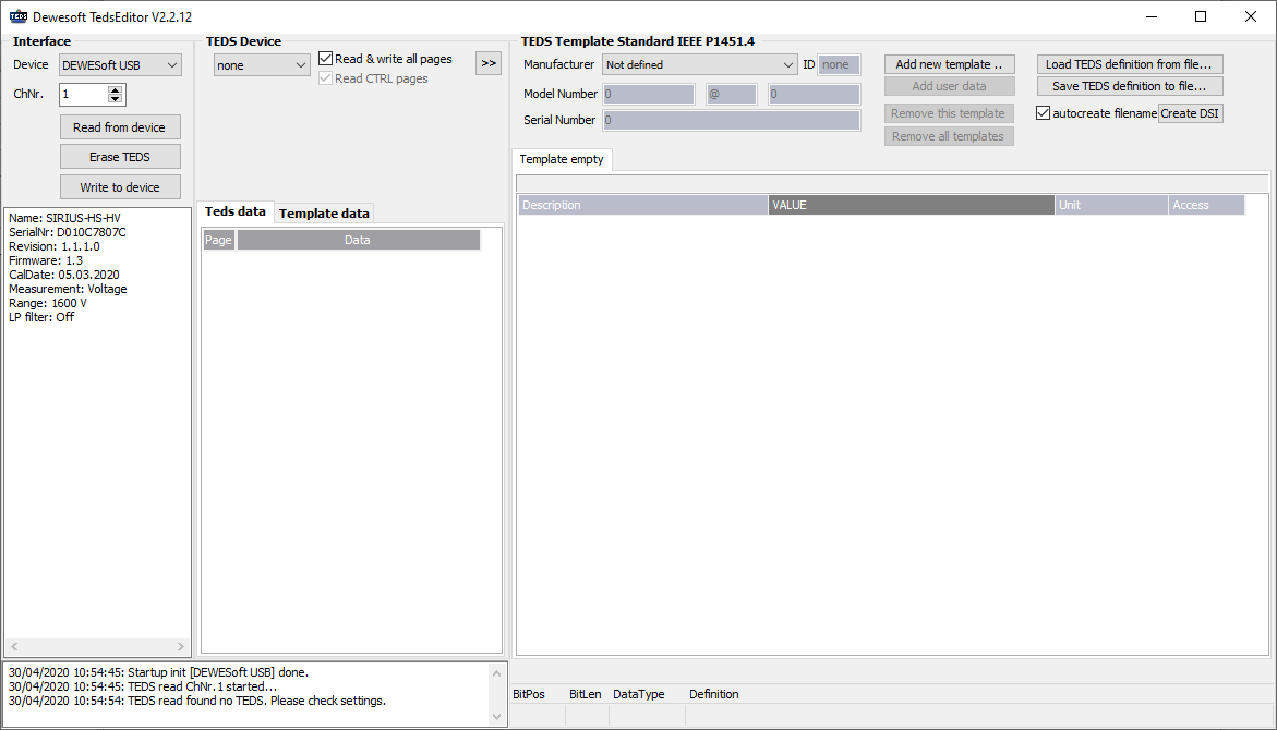
Image 11: Dewesoft TEDS Editor interface 


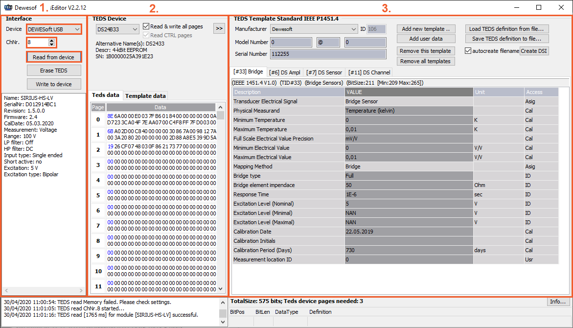
After we Read from device, the screen gets filled with information from the sensor. Before reading from the device, select the right channel number on which you have connected TEDS.

 Reading the TEDS chip from a sensorImage 12: Reading the TEDS chip from a sensor 


What we can see are three sections:

1. Interface,
2. TEDS device and
3. TEDS template.

1. Interface section

The left side is the Interface section and shows us the three Interfaces that Dewesoft allows to have - Dewesoft USB device, Amplifiers RS232, and OneWire reader.

Interface sectionImage 13: Interface section 


If we choose for example Dewesoft device in the Interface section, we also need to choose the right Channel number (ChNr.). And then we press Read from device.

On the left side we receive all the information of the amplifier or the interface: its name, serial number, calibration date, excitation, and more.

 Information about the amplifierImage 14: Information about the amplifier 

2. TEDS device section

TEDS device section shows us what device was found after we have pressed Read from device. In our case it found a DS24B33 chip. This is also the usual TEDS that we recommend among all the different TEDS device options.

TEDS Device sectionImage 15: TEDS Device section

Selecting TEDS DeviceImage 16: Selecting TEDS Device 


What we can see below the found TEDS device is also it's first (Alternative) name, short description, that shows us how many memory the TEDS has, in our example 4-kbit EEPROM and what is really unique - TEDS serial number (SN). On this point it is really important to point out that every TEDS chip has its own serial number.

3. TEDS template section

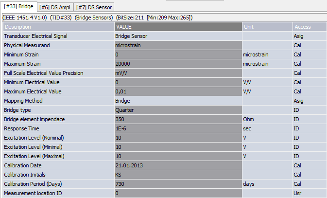
TEDS template section shows us the Manufacturer and his ID number, Model number and Serial number of TEDS. In this section we can also find detailed information, for example Bridge type, Response time,...

TEDS template section includes a lot of informationsImage 17: TEDS template section includes a lot of information


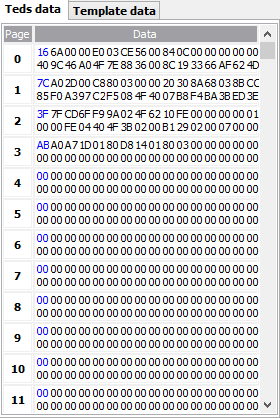
All this information is decoded from TEDS Data on the left. After every change, Template data changes, and TEDS data stays the same as it was.

Decoded information from TEDSImage 18: Decoded information from TEDS


Down at the bottom we can find all the actions that were made since we have opened the TEDS editor. All the errors will also appear in this screen.


Actions made in TEDS editorImage19: Actions made in TEDS editor 


NOTE: Calibration date and other information of TEDS can be only changed if it was created by Dewesoft or if somebody else made it with the Dewesoft tool (TEDS editor).

IMPORTANT: While using the TEDS editor, you really need to know what you are doing!

Creating new TEDS sensors

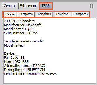
Creating a TEDS sensor from scratch is very easy. First of all, we need to write in the Manufacturer, Model number and serial number. These fields are quite limited in what we can write in, but there is a better way of doing that, so if these fields don't make you happy, read further.

When you have an empty sensor, we can add a new template by pressing the Add new template button. All standard IEEE sensors are supported. We can enter any field in the template in the user editor.

Add a new template for an empty TEDS sensorImage 20: Add a new template for an empty TEDS sensor


Now we can add additional templates. We can add a standard Calibration table, Calibration curve, or Frequency Response Curve or we can add the Dewesoft amplifier template to define all amplifier properties (Input type, Range, LP, and HP filter, ...).

Adding standard templatesImage 21: Adding standard templates 


LP filter - defines which low pass filter will be chosen for the amplifier (advanced option has also type and filter order)
User coupling - defines which high pass filter will be used (either sensor is AC or DC coupled)
Measurement - defines which measurement type amplifier is set to (voltage, bridge, potentiometer, ...)
User excitation - defines the nominal excitation voltage the amplifier is set to by default
Input type - defines either amplifier is set to a differential or single-ended mode
User range - defines the range that the amplifier must be set to
Range dual-core - defines if high-dynamic dual-core ADC technology is used (related only to Dewesoft amplifiers)

We can also add Dewesoft sensor properties by adding the option to have a longer sensor description, serial number, limits, polarity, and so on.

Dewesoft sensor propertiesImage 22: Dewesoft sensor properties


User manufacturer - this field overrides the manufacturer ID set in standard template
User model name - this field overrides the default model name (user can use alphanumeric characters of any length)
User serial number - this field overrides the default serial number (user can use alphanumeric characters of any length)
Physical measurand - defines which physical quantity sensor is measuring (according to SI unit system)
User scale - defines the sensor scale according to Dewesoft standard (so SI unit conversion can be used) - unit of measurement must comply to Dewesoft SI unit scheme
User Sensor Limits - defines the absolute minimum and maximum that sensor can measure (will be used for display purposes)
Additional bridge props - the properties for strain gage sensors not defined by the IEEE standard
Sensor polarity - defines standard sensor polarity
User Sensor offset changeable - if yes, user can change the offset at a later time (when setting up the initial load, for example)
User Sensor scale changeable - if yes, user can assign additional scale factor at a later time
Calibration info - additional info from calibration

We can also define a Dewesoft transfer curve template. This curve is used in frequency analysis to correct sensor frequency response as well as in the power module for example for current clamps sensor. We define the amplitude attenuation in % and the phase angle for a set of typical frequencies.

Once we are done defining the sensor, we can write it to the chip using Write to device button or save sensor for future use by using Save TEDS definition to file.

Dewesoft TEDS Library (TDL)

In the Dewesoft TEDS library we can find the description of how templates in TEDS editor work. With the use of this file, people should learn how to read all the information written in Dewesoft's templates. You can read all the data till the last bit, but no more than that.

You can download this text file DewesoftTEDSLibrary.zip from the download section on our Web page.


Not everyone should be allowed to change the settings stored in the sensors (e.g. only the calibration lab which creates sensors), so you can apply to be asked for a password when entering the settings.

Go to Settings and press Security on the left side of the screen. Enable the checkbox "User access password" and enter a password. If this option is not available to enable it, first set the Use admin password for entering settings, and then the User access password will become available.

 Check the User access password and enter the passwordImage 23: Check the User access password and enter the password

After that you need to define also what for would you like to use this access password. In our example, we would like to use it for editing sensors.


Now just connect the sensor with TEDS to another STG channel - in our case on image 24 from channel 7 to channel 8. You will see that all settings are overtaken correctly. It will also work on similar amplifiers, like STG-M, if the same settings are supported there. In our case settings on amplifiers are a bit different in range and values, however, all the TEDS sensor data were overtaken as it is shown on the image 24.

Image 24: Channel setup after connecting a TEDS sensor to another amplifier

When you write a TEDS chip or when a TEDS chip is detected in Dewesoft for the first time, it will also be written into the Sensor database. The TEDS has always the highest priority, if you plug it in, the Sensor database will be automatically updated with the settings from the chip.

Image 25: Enable Advanced sensor settings 


When you press Write to TEDS and "Show advanced sensor settings" checkbox is enabled, the following screen appears:

Advanced sensor settings windowImage 26: Advanced sensor settings window 


On the top of the Advanced write options window is the Lock all channel settings option, which you can disable in order to change desired locked settings. There are several options you can choose from, and few are described below:

  • Allow user to define offset - normally TEDS sensor defines the fixed scale and offset, but if this checkbox is checked, the user can additionally set sensor offset (like for zeroing)

  • Write channel name to sensor - will write the channel name to sensor stored in SensorDataBase and retrieve it when connected to the different physical channel (this is not written to TEDS)

  • Sensor max./min. limit - defines the absolute maximum and minimum (physical) value that the sensor can output. If it is set to INF, it will calculate it automatically from range and scaling. This will set Min and Max value of the channel.

  • Sensor excitation min/max - defines the limit of excitation that sensor can work from

  • Password for TEDS - Sensor can be also password protected.

When the TEDS sensor with password protection is connected to other channels, it will be read automatically, but when unlocking the sensor the user will need to enter the password.