Temperature Measurement With Thermocouple, RTD and Thermistor Sensors

Temperature is a measure of how cold or hot something is, expressed in several different scales, such as Celsius, Kelvin or Fahrenheit. Temperature can be measured with thermocouples, RTDs or thermistors.

Temperature is a physical property of matter that expresses how hot and cold it is.

Did you know that temperature is the MOST often recorded physical measurement? Knowing the temperature is critical for the correct operation of everything from the human body to an automobile engine, and everything in between. 

We need to know the temperature of objects for an almost infinite number of purposes. Temperature is often an indicator that something is wrong: perhaps you have a fever, or the brake pads on your car are about to fail, or a turbine in an energy plant is running too hot. You get the idea. 

Temperature is measured with one or more kinds of temperature sensors. There are several available on the market today:

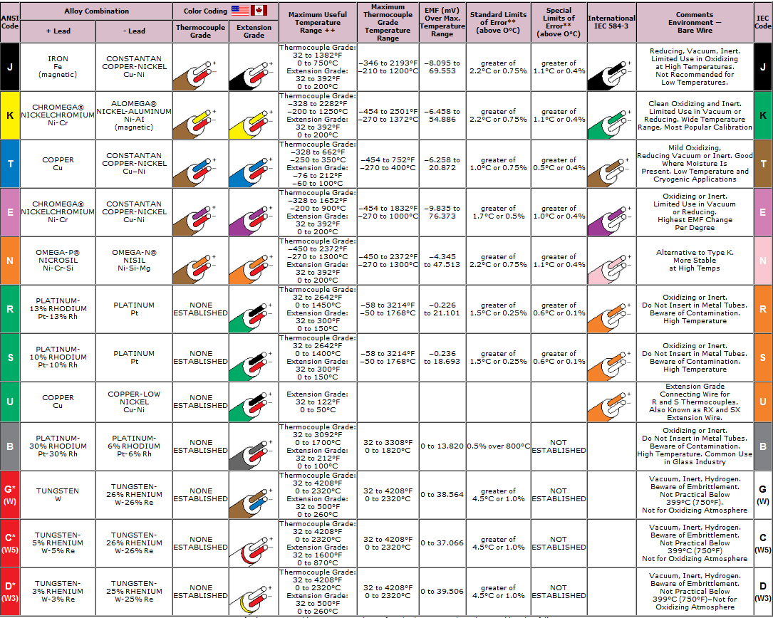
  • Thermocouple sensors
  • RTD sensors
  • Thermistor sensors
  • Infrared temperature sensors

The most common scales are the Celsius scale (formerly called centigrade, denoted °C), the Fahrenheit scale (denoted °F), and the Kelvin scale (denoted K), the last of which is predominantly used for scientific purposes by conventions of the International System of Units (SI).

  • Celsius or centigrade scale which is the most often used scale. For this scale, the freezing point of water is considered to be zero degrees, the boiling point is 100 degrees, and each degree in between is an equal 1/100th of the distance between freezing and boiling.
  • Fahrenheit scale is still widely used in the United States. On the Fahrenheit scale, freezing is 32 degrees and boiling is 212 degrees (180 degrees difference).
  • Kelvin scale was created to be more scientific. It is the base unit of thermodynamic temperature measurement in the International System (SI) of measurement. It is defined as 1/ 273.16 of the triple point (equilibrium among the solid, liquid, and gaseous phases).

Graphical comparison of scales:

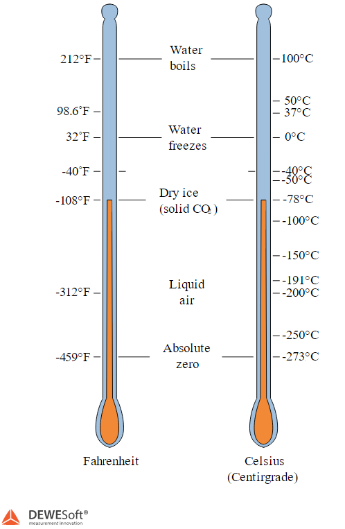
Image 1: Comparison of Fahrenheit and Celsius temperature scale


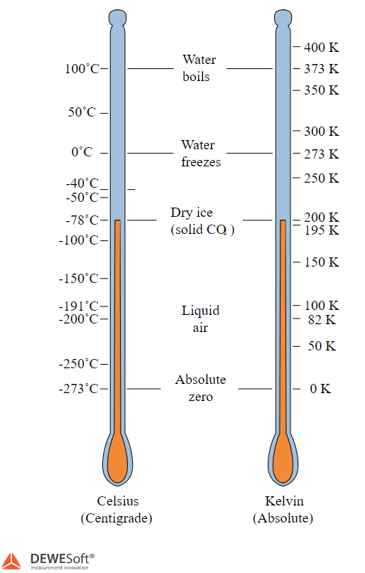
Image 2: Comparison of Celsius and Kelvin temperature scale


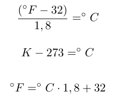
Conversion of temperature between different scales can be expressed with the following equations:

The lowest theoretical temperature is absolute zero, at which no more thermal energy can be extracted from a body. Experimentally, it can only be approached very closely, but not reached, which is recognized in the third law of thermodynamics.

Temperature is important in all fields of natural science, including physics, chemistry, Earth science, medicine, and biology, as well as most aspects of daily life.

Thermocouple Sensors

Thermocouples are cheap, interchangeable, have standard connectors, and can measure a wide range of temperatures. The main limitation is accuracy. System errors of less than 1°C can be difficult to achieve.

A thermocouple is created when two dissimilar metals touch and the contact point produces a small open-circuit voltage as a function of temperature.

You can choose between different types of thermocouples named by capital letters that show their compositions according to American National Standards Institute conventions. The most common thermocouple types of thermocouples include B, E, K, N, R, S, and T.


Image 3: Thermocouple sensor


ADVANTAGESDISADVANTAGES
  • Self Powered
  • Simple
  • Rugged
  • Inexpensive
  • Wide Variety
  • Wide Temp Range
  • Non-Linear
  • Reference Required
  • Low Voltage
  • Least Stable
  • Least Sensitive
Image 4: Linearisation curve from different types of thermocouple sensors


RTD Sensors - Resistance Temperature Detector

An RTD is a device made of coils or films of metal (usually platinum). When the RTD is heated, the resistance of the metal increases; when it gets cooled, the resistance decreases. Passing a current through an RTD generates a voltage across the RTD. By measuring this voltage, you can determine its resistance and that's how its temperature. The relationship between resistance and temperature is relatively linear. Typically, RTDs have a resistance of 100 Ohm at 0 °C and can measure temperatures up to 850 °C.


Image 5: RTD sensor


ADVANTAGES DISADVANTAGES
  • Most Stable
  • Most Accurate
  • More Linear than Thermocouple
  • Expensive
  • Current Source Required
  • Small R
  • Low absolute Resistance
  • Self-heating
Image 6: RTD sensor response curve


Thermistor Sensors

NOTE: Thermistors are mostly used in electronics circuits and have little practical use when it comes to measuring with Dewesoft. Thus, we shall only give a small overview of them and omit them from further discussion.

A thermistor is a piece of semiconductor made of metal oxides that are pressed into a small bead, disk, wafer, or other shape and sintered at high temperatures. Lastly, they are coated with epoxy or glass. As with RTDs, you can pass a current through a thermistor to read the voltage across the thermistor and determine its temperature. However, unlike RTDs, thermistors have a higher resistance (2,000 to 10,000 Ohm) and much higher sensitivity (~200 Ohm/°C), allowing them to achieve higher sensitivity within a limited temperature range (up to 300 °C)


Image 7: Thermistor sensor


ADVANTAGES DISADVANTAGES
  • High Output
  • Fast
  • Two-wire ohms measurement.

  • Non-Linear
  • Limited Temperature Range.
  • Fragile
  • Current Source required.
  • Self-heating


Image 8: Temperature response of the thermistor


We already mentioned that thermocouples are the most often used temperature sensors.

A thermocouple is made of at least two metals that are joined together to form two junctions. One is connected to a body whose temperature will be measured; this is the hot or measuring junction. The other junction is connected to a body of known temperature; this is the cold or reference junction. Therefore the thermocouple measures the unknown temperature of the body with reference to the known temperature of the other body, which is in line with the Zeroth law of thermodynamics which states that: When two bodies are separately in thermal balance with the third body, then the two are also in thermal balance with each other". Because of this, we need to know the temperature at the cold junction if we wish to have an absolute temperature reading. This is done by a technique known as cold junction compensation (CJC).

Typically CJC temperature is sensed by a precision RTD sensor in good thermal contact with the input connectors of the measuring instrument. This second temperature reading, along with the reading from the thermocouple itself is used by the measuring instrument to calculate the true temperature at the thermocouple tip. By combining the signal from this semiconductor with the signal from the thermocouple, the correct reading can be obtained without the need or expense to record two temperatures.

Understanding cold junction compensation is important since any error in the measurement of the cold junction temperature will lead to the same error in the measured temperature from the thermocouple tip. As well as dealing with the CJC, the measuring instrument must also compensate for the fact that the thermocouple output is non-linear. The relationship between temperature and output voltage is a complex polynomial equation (5th to 9th order depending on thermocouple type). High accuracy instruments such as Dewesoft instruments store thermocouple tables in devices and compensate the results to eliminate this source of error.


Working principle of Thermocouples

Now let's take a look at the working principle of every Thermocouple. The working principle is based on the Seebeck, Peltier, or Thomson effect.

1. Seebeck effect prescribes that a circuit made from two dissimilar metal, with junctions at a different temperature, induces a voltage difference between the junctions.


Image 9: Seebeck effect 


2. Peltier effect is the opposite of the Seebeck effect. Instead of using heat to induce a voltage difference, it uses a voltage difference to induce heat.


Image 10: Peltier effect


3. Thomson effect states that if an electrical current flows along a single conductor while a temperature difference exists in the conductor, thermal energy is either absorbed or rejected by the conductor, depending on the flow of the current. More specifically heat is liberated if an electric current flows in the same direction as the heat flows; otherwise, it is absorbed.


Image 11: Thomson effect


The circuit of every Thermocouple must be composed of two dissimilar metals, for example, A and B. These two metals are joined together to form two junctions, p, and q, which are maintained at the temperatures T1 and T2 respectively. Let's not forget, that thermocouple cannot be formed if there is just one junction. 

If the temperature of both the junctions is the same, equal and opposite electromotive force will be generated at both junctions and the net current flowing through the junction is zero. If the junctions are maintained at different temperatures, the electromotive force will not become zero and there will be a net current flowing through the circuit. 

The total electromotive force flowing through this circuit depends on the metals used in the circuit as well as the temperature of the two junctions. An ammeter is connected in the circuit of the thermocouple. It measures the amount of electromotive force flowing through the circuit due to the two junctions of the two dissimilar metals maintained at different temperatures.

Thermocouples can be made from almost any type of metal, but there are many standard types used because their output voltages and large temperature gradients can be predicted. 

Each calibration has a different temperature range and the environment, although the maximum temperature varies with the diameter of the wire used in the thermocouple. Although the thermocouple calibration dictates the temperature range, the maximum range is also limited by the diameter of the thermocouple wire. 

That is, a very thin thermocouple may not reach the full temperature range. The four most common calibrations of Thermocouples are J, K, T, and E. There are high-temperature calibrations like R, S, C, and GB. 

If you want to choose the right Thermocouple for your measurement, you need to look at a number of different factors, like:

  • what are the maximum and minimum temperatures that the thermocouple will detect, 
  • what are the cost limits, 
  • what error tolerances are acceptable for a certain application, 
  • what is the furnace atmosphere, what is the expected life of certain thermocouple type, 
  • what is the required time response, 
  • will the use of the thermocouple be periodical or continuous, 
  • will the thermocouple be exposed to bending or flexing during its life, and 
  • what is the immersion depth?

Characteristics of different thermocouples:


Image 12: Characteristics of different thermocouples


Types of thermocouple fabrications:

Beaded Wire Thermocouple

Image 13: Beaded wire Thermocouple


This type of Thermocouples is the simplest form of all of the thermocouples. It is made of two pieces of thermocouple wire joined together.

Because of this bead, this type of thermocouples has a lot of limitations. Beaded wire thermocouple mustn't be used with liquids that could corrode or oxidize the thermocouple alloy.

In general, beaded wire thermocouples are a great choice if we measure gas temperature. Since they can be made very small, they also provide a very fast response time.

We can actually build these thermocouple types ourselves by buying a thermocouple wire and joining the hot point together. Please note that soldering is not a good option since it adds a third material which will increase inaccuracy. The bigger the junction is, the slower the response of the thermocouple.

NOTE: This thermocouple type is not electrically isolated, so it is advisable to use isolated amplifiers such as Dewesoft Krypton.

Thermocouple Probe


Image 14: Thermocouple probe


A thermocouple probe is made of a thermocouple wire that is housed inside a metal tube, which is made of stainless steel or Inconel.

Inconel supports higher temperature ranges than stainless steel, however, stainless steel is often preferred because of its broad chemical compatibility.

The tip of the thermocouple probe can be made in three different styles. Grounded, ungrounded, and exposed.

With a grounded tip, the thermocouple is in contact with the sheath wall. A grounded junction provides a fast response time, but it is the most susceptible to electrical ground loops.

In ungrounded junctions, the thermocouple is separated from the sheath wall by a layer of insulation. Response time is slower than the grounded style, but it offers electrical isolation

Exposed junction types have the tip of the thermocouple outside the sheath wall with an exposed junction. They offer the best response time but are limited in use to dry, noncorrosive and non-pressurized applications.


Image 15: Thermocouple Tip Styles


Surface Probe

Image 16: Surface probe


These types of thermocouples are great for any surface measurements. Because the thermocouple can be fitted with a rotating mechanism, so we can measure the temperature of a moving surface.


RTD is a sensor that measures the change in temperature by correlating it with the change in the resistance of the RTD element. 

These types of sensors are made by wrapping a fine, coiled wire around a ceramic or glass core. The sensor is usually quite fragile, so it is often placed inside a sheathed probe to protect it. The relationship between resistance and temperature is relatively linear and it can typically measure temperatures up to 850 °C.

RTDs are generally considered to be among the most accurate temperature sensors available. In addition to offering very good accuracy, they provide excellent stability and repeatability. They also feature high immunity to electrical noise and are, therefore, well suited for applications in process and industrial automation environments, especially around motors, generators, and other high voltage equipment. 

The best known RTD is the Pt100.

The name tells us that the base material is Platinum and nominal resistance is 100 Ohms at 0 deg C. The accuracy is better than thermocouples - below 0.3 deg C. The primary concerns when selecting among the various RTD fabrication types are the temperature range and accuracy requirements. The four main configurations are wire-wound, film, coil, and hollow annulus. Wire-wound RTD is built by simply winding a small sensing wire around a mandrel constructed of electrically non-conductive material.

Cost wise this style is similar to the inner coil element. It is not as accurate as the inner coil, style but is more rugged


Image 17: RTD sensor


Thin film RTD is probably the most popular design because of its rugged design and low cost. RdF certified suppliers deposit a thin layer of platinum in a resistance pattern on a ceramic substrate, which is then coated with a thin layer of glass.

One advantage of this type of sensing element is that greater resistance can be placed in smaller areas than with other elements. As an example, a 1000 Ohm sensor is typically manufactured no larger than 1.6mm wide x 2.6 mm long. Thin-film elements are cheaper and more widely available because they can achieve higher nominal resistances with less platinum.


Image 18: Thin-film RTD sensor


Coiled element RTD is manufactured by inserting a helical coil of platinum sensing wire into the internal bores of an insulating mandrel. The powder is packed around the coil to prevent it from shorting and to provide vibration resistance during service. This type is the most accurate. It is, however, more expensive to manufacture and does not perform well in high vibration applications.


Image 19: Coiled RTD element


Hollow annulus RTD uses an open-ended metal winding mandrel to provide a faster time response. This element has the advantages of being completely sealed and having an extremely fast time response, but it is the most expensive of the four types. The large winding diameter enables high resistance sensors to perform optimally in cryogenic fluid applications, so it is no surprise that these sensors are used in the aerospace and nuclear industry.


Image 20: Hollow annulus RTD sensor


Many people don't know which sensor to choose for their measurements. That's why we need to make a comparison, by explaining the advantages and disadvantages of Thermocouples and RTDs. First let's take a look at the criteria of each temperature sensor.

CRITERIATHERMOCOUPLERTD
Measurement rangefrom -267°C to 2316°Cfrom -240°C to 649°C
Interchangeabilitygoodexcellent
Long-term stabilitypoor to fairexcellent
Accuracymediumhigh
Repeatabilitypoor to fairexcellent
Sensitivity (output)lowgood
Responsemedium to fastgood
Linearityfairgood
Self-heatingnolow
Tip (end) sensitivityexcellentfair
Lead effecthighmedium
Sizesmall to largemedium to small

Now let's take a look at the advantages and disadvantages of Thermocouples and RTDs.

SENSOR ADVANTAGES DISADVANTAGES
THERMOCOUPLE

- Inexpensive
- No resistance lead wire problems
- Fastest response
- Simple and rugged
- High-temperature operation
- Tip (end) temperature sensing

- Least sensitive
- Non-linear
- Low voltage
- Least stable, repeatable
RTD

- Good stability
- Excellent accuracy
- Contamination resistant
- Good linearity
- Area temperature sensing
- Very repeatable temperature measurement

- Marginally higher cost
- Current source required
- Self-heating
- Slower response time
- Medium sensitivity to small temperature changes

Advantages of Thermocouples in comparison to RTDs

If we make a comparison, regarding the cost, we can see, that Thermocouples cost three times less than RTDs. Besides all that, thermocouples are designed to be more durable and react faster to all the changes in temperature. Due to their construction, the RTDs are somehow more fragile than the thermocouples and are not self-powered.

A current must pass through the RTD to provide a voltage that can be measured. The RTD also experiences more thermal shunting ( The act of altering the measurement temperature by inserting a measurement transducer). But the biggest difference between them is their measurement range. While most RTDs are limited when it comes to high temperatures (max 538°C), Thermocouples can be used to measure up to 2300°C.


Advantages of RTDs in comparison to Thermocouples

As we can see from the table, the main strength of RTDs is the accuracy of their readings and also their test-retest reliability. Test-retest reliability means, that results are the same no matter how many trials of measurement there were. The design of such sensors ensures that RTDs are producing stable readings longer than Thermocouples. Besides all that, the design of RTDs makes the received signals more robust, which makes calibration easier.

So ... which sensor to choose?

If you want to save money and buy more durable sensors that can measure high-temperature range, thermocouples are the right choice. But if you want to have more accurate measurements in a limited temperature range, choose RTDs.


Now that we are acquainted with how different sensors work and know the pros and cons of different sensors types, its time to see how it's done in DewesoftX data acquisition software. All of Dewesoft DAQ systems ( KRYPTON, IOLITE, SIRIUS, and DEWE-43 ) support temperature measurements. There are various different temperature data loggers available for temperature recording.

They support both thermocouple and RTD sensors. The KRYPTON has the option of using direct mini thermocouple ports or DSI adapters, while SIRIUS and DEWE-43 both only support measuring temperature through the use of DSI adapters. 

We are going to learn how to set up and perform measurements for each hardware type separately. Then we are going to set up all the hardware at once and take a measurement of a certain reference point, to compare the accuracy of the hardware.

Important: DEWE-43A does not have isolated inputs and should be handled with care or else you risk losing your equipment.

Before we can measure anything we need to properly set up the channels. This is done in the channel setup screen.

To set the appropriate channels, we simply click the Unused/Used button, as shown in the picture below ( Note that we set two channels because we will use two thermocouple sensors). Then we go to Channel setup screen for each channel, either by pressing the Setup button on the right end of Channel setup or simply by double-click on the selected channel in the device preview.

The pictures below show the Channels setup of KRYPTON, SIRIUS, and DEWE-43.

Image 21: Channel setup on KRYPTON 


Image 22: Channel setup on SIRIUS


Image 23. Channel setup on DEWE-43


Let's take a look at how to set up KRYPTON. Since KRYPTON has universal input, we have to choose the appropriate thermocouple type for the connected sensor manually in channel setup This is done by selecting the correct sensor type under Range. Due to different non-linear scaling, it is important to choose the right type since scaling tables are different. Please note that Dewesoft shows two different color codes - ANSI (American standard) and IEC (European standard).

Image 24: Thermocouple setup on KRYPTON


SIRIUS and DEWE-43 have a slightly different setup. They both automatically detect what type of sensor is connected and show the appropriate scaling.

Image 25: Thermocouple setup on SIRIUS with DSI-TH-K adapter


We can also set an RTD sensor on the SIRIUS, using one of the STG ports. Unlike the thermocouple, the RTD is not automatically set and must be set in channel setup. This is done by simply selecting Temperature, under the Measurement option.

Image 26: RTD sensor connected to SIRIUS


Then the correct sensor type will be displayed on the screen as shown in the image below.

Image 27: Channel setup of an RTD sensor


On this point, we are going to make a short temperature measurement in Dewesoft X data acquisition software.

For this experiment, we will use:

Required hardwareKRYPTON 8xTH
Required softwareDewesoft X
Setup sample rate

100 Hz

The image below shows the channel setup for temperature measurements. We can see two temperature sensors connected to KRYPTON 8xTH.

For this experiment, we will use two drinks - a hot cup of tea and a cold, refreshing cocktail. The purpose of this experiment is to measure the temperature difference between these two beverages.

Image 28: Demo equipment for temperature measurement


After we connect all the hardware together, prepare a tasty cocktail and tea, set up everything in Dewesoft X, as discussed before, we can finally do the measurement.

As we can see in the image below we have immersed the first thermocouple in the cold cocktail and the second one in the hot tea.

Image 29: One thermocouple immersed in a cold cocktail and the second one in a hot cup of tea


In Dewesoft X software, we go to Measure mode and choose the recorder, if it wasn't shown automatically when you entered measure mode. As we can see, the settings started to acquire data and now we can finally measure the temperature difference.

At first, when both sensors are at room temperature, the difference is only 3 K. 

Image 30: Both sensors are at room temperature, the difference is only 3K

 Then we immerse both sensors in their designated liquid, the first one in the cold cocktail, and the second one in the hot tea, at the same time. The temperature difference is now 44 K. 

Image 31: One sensor is immersed in a hot liquid and one in a cold liquid. The difference is 44K. 


Now that we know how to do a basic temperature measurement in Dewesoft X, it's time for something a little more interesting. In this experiment, we are going to compare a thermocouple sensor to an RTD sensor.

The equipment we are going to use:

Required hardwareSIRIUS instrument with at least 2 STG ports, thermocouple, and an RTD sensor, hot and cold beverage
Required softwareDewesoft X data acquisition software
Sample rate100 Hz

First, we prepare and connect all the equipment and beverages, then we run and setup Dewesoft X. Note that while you only require 2 sensors for this experiment, you can use more to get a better picture of the small differences between sensors. For this particular measurement, we used an RTD sensor and two thermocouple sensors for comparison.

The thermocouple sensors have quicker stabilization periods compared to the RTD sensor. It only takes them about 6 seconds to stabilize, compared to the RTD's 20 seconds. It is worth mentioning that after the stabilization period the measurement of the RTD will be more accurate.

Here we see a more dynamic measurement. This was done by quickly alternating the sensors between the hot and cold beverages. It is apparent that the thermocouple vastly outclasses the RTD in terms of responsiveness. The differences between the thermocouples themselves are also noticeable. This is because the sensors are not the best and are a bit used.

  Image 32: Time that it takes to stabilize the sensors


The choice of proper equipment is important when doing measurements. Sometimes you need better accuracy, while other times you need better flexibility. 

We will compare the accuracy of the:

  • KRYPTON: KRYPTON-8xTH EtherCAT data acquisition system with thermocouple mini connector
  • SIRIUS: SIRIUSi-8xSTG data acquisition system with DSUB9 input connector
  • DEWE-43A data acquisition system with DSUB9 connector and DSI adapter

At different ambient temperatures to help you chose the right equipment for you.

The measurements were taken in a temperature chamber, with ambient temperatures of -10°C, 23°C and 40°C for all equipment and also -35°C and 80°C for the KRYPTON . A precision calibrator, along with type T thermocouple cables, was used to insure constant temperature inputs of -200°C, -100°C, 0°C, 100°C, 200°C, 300°C and 375,5°C. 

The precision calibrator uses a micro thermocouple output, so we have to use MSI adapters for the SIRIUSi-STG-DSUB9 and DEWE-43A since they don't have prebuilt micro thermocouple input.The sample frequency for SIRIUSi-STG-DSUB9 and DEWE-43A was set to 20000 Hz while the KRYPTON-8xTH was clocked at 100 Hz. Because of the signal noise, we used averaged values. Note that we could have set a low pass IIR filter.

The error calculation is shown in the below chart:

DEWE-43A0,1% of reading + 0,1mV
SIRIUSi-STG-DSUB90,05% of reading +0,1mV (0.01% if using "Balance Amplifiers")
KRYPTON - 8xTH0,02% of reading +10µV

A picture showing the difference between the Actual value and the Averaged/Filtered values. This was set up using DEWE-43A:

The graph below shows the maximum error according to the specifications of the selected hardware setup. It was calculated by using the specifications of the hardware and the voltage-per-degree chart of the applied thermocouple type (in our case the T -type). For the SIRIUSi-STG-DSUB9 and DEWE-43A, we also took the error of the MSI-BR-TH-T adapters into account, using the information specified by the provider. This is what causes the sudden changes in the value, most notably at -100°C. We see that the measurement should be quite accurate from about -100°C on. This is due to the nature of the T-Type thermocouple.

At this point we would also like to include theoretical error graphs for C, J and K type thermocouples since they are supported by their corresponding MSI-BR-TH adapter (the KRYPTONcan support any type, of course ).

Note that the response of the SIRIUS and DEWE-43 are exactly the same:


Below are the results of the measurements. The little dots represent the channels that were used to take the measurements. All the measurements were taken with a set sensor input, but we manually spaced the measurement groups 5°C apart on the graph for clarity.

The results show that all measurements are well within the accepted range of error. The best results were achieved with the SIRIUSi-STG-DSUB9 and KRYPTON -8xTH. They both errors of less than 1°C in the relatively linear part of the T-type thermocouple (as see on the graph on the previous page), with slightly larger errors in the non-linear part. 

The SIRIUSi-STG-DSUB9 had the most accurate results because of its "Balance amplifiers" feature, but the KRYPTON-8xTH had the overall best results because of its good accuracy and a wide temperature range. The DEWE-43A was less accurate than the KRYPTON-8xTH and SIRIUSi-STGM-DSUB9, but still had good results.