Dewesoft Video Acquisition

Dewesoft X video acquisition module offers the possibility to acquire video signals synchronised together with other sources like analog, digital, counter, CAN, XCP, etc. A wide range of cameras are supported from simple Direct X web cameras, to high-speed, rugged DS-CAM cameras and IR thermo-vision cameras from FLIR.

Dewesoft X video acquisition module offers the possibility to acquire video signals together with other sources. A wide range of cameras are supported:

  • Low-speed cameras (up to 30 FPS): any DirectX compatible camera
  • Medium speed cameras (up to 600 FPS VGA resolution): Dewesoft DS-CAM cameras
  • High-speed cameras (up to 20.000 FPS at VGA resolution): where we combine data and video in post-processing or directly use the Photron driver inside Dewesoft X (please consult the user's manual for details)
  • Thermovision cameras: Optris thermovision cameras


Required hardwareSirius, Dewe-43, Webcam, DS-CAM
Required softwareProf (for DS-CAM support)
Setup sample rateAt least 1 kHz


For applications requiring video which is truly synchronized to the dynamic sample rate, there is support for DS cameras. A high-quality image with the automatic shutter speed (selectable) is controlled directly by the A/D card, which generates a pulse to drive the camera. The result is a stunning correlation between each frame and the data.

Thermo cameras are supported by Optris, and Ultra-High-Speed cameras from Photron can acquire more than 2 million frames per second but in limited resolution.


DS-CAM-88c, DS-CAM-120c (gigabit-ethernet camera)


DS_CAM-88c cameraImage 1: DS-CAM-88c camera


A DS-CAM-88 has the following specifications:

  • resolution
    • 640x480 at 88 fps
    • 320x240 at 167 fps
    • 160x120 at 289 fps
  • auto-shutter
  • auto-gain
  • auto white-balance
  • color

DS-CAM-175c, DS-CAM-320c (gigabit-ethernet camera)


DS-CAM-175c cameraImage 2: DS-CAM-175c camera

 
Specifications:

  • power-over-ethernet option
  • the best performance with SIRIUS S-BOX
  • IP67 version available
  • auto-shutter
  • auto-gain
  • auto white-balance
  • color
  • DS-CAM-175chas the following specifications:
    • 1456x1088 at 68 fps
    • 640x480 (VGA) at 178 fps
  • DS-CAM-320chas the following specifications:
    • 728x544 at 266 fps
    • 640x480 (VGA) at 328 fps

DS-CAM-600m, DS-CAM-600c, DS-CAM-600cw (gigabit-ethernet camera) 


DS-CAM-600c cameraImage 3: DS-CAM-600c camera


Specifications:

  • full HD resolution (1920x1080)
  • real-time onboard JPEG compression
  • power-over-ethernet option
  • the best performance with SIRIUS S-BOX
  • IP67 version available
  • color and monochrome
  • DS-CAM-600bw/chas the following specifications:
    • 1920x1080 (HD) at 300 fps
    • 640x480 (VGA) at 600 fps

Applications

All DS-CAM cameras were designed to be high-shock and vibration resistant.

The DS-CAM cameras can run in triggered (sync) and free-run mode. The video is captured by real-time data streaming, even at full resolution! Therefore, a Gigabit-Ethernet port is required.

The system requirements for GigE cameras are:

  • Gigabit Ethernet LAN port
  • Dewesoft X
  • (Clock possibility)
  • Core2Duo CPU

The applications at which the cameras are used:

  • machine diagnostic
  • product quality check
  • non-destructive testing
  • research and development
  • automotive crash testing
  • impact tests
  • logistics and transportation
  • manufacturing

Specifications

If you have multiple DS-CAM cameras, we can provide adapters for syncing, powering, and connecting multiple cameras to Dewesoft instruments.

CAM-BOX

Adapter box for connecting one DS-CAM-88/120 to the Dewesoft instrument. Combines Sync and Power to the camera connector. 


CAM-BOX1

Adapter box for connecting up to 4 DS-CAM-88/120 to the Dewesoft instrument. Combines Sync and Power to the camera connector. External GigE switch required.

CAM-BOX1 Image 4: CAM-BOX1


CAM-BOX2

Distribution box for connecting up to 4 x DS-CAM-88/120 to the Dewesoft instrument. Wide range power supply input (9-36 VDC), integrated GigE switch.


CAM-BOX2Image 5: CAM-BOX2


CAM-BOX3

Distribution box for connecting up to 4 x DS-CAM-600 to the Dewesoft instrument. Wide range power supply input (9-36 VDC), integrated GigE switch with 4 x PoE; SIRIUS chassis with 1.5 U height.


CAM-BOX3Image 6: CAM-BOX3


3rd party camera support

If your application requires video you are not limited to using our own DS-CAM cameras. 

Dewesoft X software supports all compatible Direct X cameras as well as 3rd party Optris thermal and Ultra-High-Speed cameras from Photron. See the complete list of supported cameras. All camera sources are synchronized to analog data.


Third party cameras supported in DewesoftImage 7: Third-party cameras supported in Dewesoft 


The DS-CAM-88c/DS-CAM-120c are high-speed Gigabit-Ethernet cameras with the following key data:

  • DS-CAM-120c: 120 fps @ VGA (640x480)
  • DS-CAM-88c: 88 fps @ VGA (640x480)
  • Color
  • Auto-gain
  • Auto-shutter (also fixed shutter possible)
  • Auto-white balance
  • Triggered and free-run mode
  • Standard C-Mount
  • Small compact form factor
  • Low power consumption
  • Ruggedized (high-shock and vibration resistant, aluminum housing)
  • Real-time data streaming with full resolution


Image 8: DS-CAM-88c


The camera supports the high-performance industrial standard GigE Vision. The standard introduced in 2006 provides a framework for transmitting high-speed video and related control over Ethernet networks.

The benefits are high-speed data transfer rates up to 1GBit/s (based on 1000Base-T) connectable to every standard GigE Ethernet port and cable lengths up to 100m.

Dewesoft uses OptoStream SDK for GigE communication with cameras that support the GigE Vision standard.

Important: For best performance, we recommended using an SSD for storing data. A disk write rate of 100 MByte/s should be established, especially if using more than 1 camera!

System requirements:

  • 1 Gigabit-Ethernet port
  • Good PC performance (Core i5 CPU or better recommended, 4 GB RAM)
  • Dewesoft X
  • The latest OptoMotive OptoStreamSDK
  • The latest Dewesoft GigE driver (cdv)

Technical specifications

Optical


DS-CAM-88cDS-CAM-120c
Image sensorSony IT ICX414AL/AQ with HAD microlens, progressive scanSony IT ICX618AL/AQ with Exview HAD CCD II microlens
Sensor typeCCDCCD
Optical size1/2 "1/4 "
Effective chip size6.5 x 4.9 mm4.46 x 3.80 mm
Cell size9.9 x 9.9 um 5.6 x 5.6 um 
Picture size (max)656 x 492 pixel646 x 492 pixel
ADC14 bit14 bit
Gain control0 - 35 dB; auto-gain0 - 32 dB; auto-gain
Exposure time26 us - 60 s; auto-shutter58 us - 60 s; auto-shutter
Smart functionsauto-white balance, color correction, edge filter (sharpness), hue, sat.auto-white balance, color correction, edge filter (sharpness), hue, sat.
Max, frame rate (at full resolution)88 fps120 fps


Power

Supply voltage8 to 30 VDC8 to 30 VDC
Power consumption<3,6 W (@ 12 VDC)<3,7 W (@ 12 VDC)
Power-over-ethernetoptionaloptional


Trigger input

Voltage level representing logical 00.0 ... 1.0 V DC
Undefined state between 0 and 11.0 ... 3.0 V DC
Voltage level representing logical 13.0 ... 24.0 V DC
Absolute maximum voltage (above → damage!)36 V (only with an external resistor of 3.3 kOhm in series)


Digital output

Maximum current source for output20 mA, open emitter


Mechanical

External housing (h x w x l)86.4 x 44.0 x 29.0 [mm]
Housingaluminum case
Weight< 200 g (without lens)
Storage temperature-10 °C .. +70 °C (14 °F .. +158 °F)
Operating temperature5 °C .. +45 °C (+41 °F .. +113 °F)
Operating humidity25% .. 80% (no condensation)
Storage humidity25% .. 95% (no condensation)
Lens mountC-mount (CS-mount optional)
ConnectorsScrew mount Ethernet RJ45; EIAJ (Hirose) 12 pin (matching part: Hirose
HR10A-10P-12S(73))
ConformityCE, FCC Class B, RoHS, GigE Vision, GenICam

Connections

On the rear side of the camera, there are two connectors. The 12pin HIROSE connector (matching part: Hirose HR10A- 10P-12S(73)) contains the power, trigger, and other digital pins. Ethernet connector pinout according to the standard.

Connection scheme for DS-CAM-88c or DS-CAM-175cImage 9: Connection scheme for DS-CAM-88c or DS-CAM-175c


Power/trigger connector pinout

12pin Hirose connector (matching part: Hirose HR10A-10P-12S(73)) on camera rear side


12-pin Hirose connectorImage 10: 12-pin Hirose connector


PIN #SIGNAL
1GND (for Power and RS232)
2Power (+8...+30 V DC)
3-
4Camera In 1 (TRIGGER)
5-
6Camera Out 1 (open emiter, max. 20 mA)
7Camera In GND
8RxD (RS232)
9TxD (RS232)
10Camera Out Power (for digital outputs)
11Camera In 2
12Camera Out 2

SIRIUS connection example

In image 11, you see a typical SIRIUS measurement instrument, consisting of one SBOX unit (integrated PC) on the bottom and one SIRIUS slice on top (from the rear side).

The camera is directly connected to the Gigabit-LAN port. The second cable to the camera contains the power (from SBOX Power out) and the trigger, connected to the SYNC port of the SIRIUS slice. The camera frames are now in perfect sync with the analog data acquired by Dewesoft.

Note: Even if the camera is connected, syncing to other SIRIUS devices is still possible, because there are different pins used on the SYNC port for triggering/synching.


Sirius connection exampleImage 11: Sirius connection example


Connecting multiple cameras

If you need to connect more than one camera, there is a special CAM-BOX2 available, which consists of:

  • wide-range voltage input (9-36V)
  • an industrial Gigabit-Ethernet-Switch (without Power-over-Ethernet! No supply for DS-CAM-600!)
  • Power and Sync distribution for up to 4 cameras.
  • Small dimensions: 115 x 62 mm (front) and 135 mm deep


Connection of three camerasImage 12: Connection of three cameras


Camerabox connector (mating cable connector: FGG.1B.307CLAD52)


Camerabox 7-pin connectorImage 13: Camerabox 7-pin connector


Power supply (mating cable connector: FGJ.1B.302CLLD42Z)


Power supply 2-pin connectorImage 14: Power supply 2-pin connector


Sync connector (mating cable connector: FGG.00.304CLAD27Z)


Sync 4-pin connectorImage 15: Sync 4-pin connector


Connections overview


Connection overviewImage 16: Connection overview 


Benchmarks

The following tests were done with SIRIUS SBOX and 1 to 4 cameras connected to the CAM-BOX2. Setup:

  • 1 to 4 cameras connected over CAM-BOX2
  • SBOX: 128GB SSD -> max 190 Mbyte/s write rate
  • CPU: Intel Core i7 QM57; 2.0GHz; 4GB RAM
  • camera(s) clocked by SIRIUS
  • Dewesoft X
  • OptoMotive OptoStreamSDK
  • GigE Camera driver (Plugin)
  • storing data to file, video buffer stable around 0.1%
  • with checked "optimize for switched network"

Achieved frame rates (fps)

Number of CamerasX resY resDS-CAM 88cDS-CAM-120c
164048088120
320240165
195
320
120280
300
2640
480
88
120
320
240
165
195
320
120
280
210
3640
480
88
90
320
240
165
195
320
120
280210
4640
480
88
60
320
240
165195
320
120
280
210


Results (FPS) should be considered only as approximate MAX values. Writing speed of disk may be limiting factor (we used SSD). We recommend testing cameras with your setup at about 0.8*max FPS and higher to find where corrupted image, frame lost or buffer overrun will occur.


The DS-CAM-175c, DS-CAM-320c are high-speed Gigabit-Ethernet cameras with the following key data:

  • DS-CAM-175c: 178 fps @ VGA (640x480)
  • DS-CAM-320c: 328 fps @ VGA (640x480)
  • Color
  • Auto-gain
  • Auto-shutter (also fixed shutter possible)
  • Auto-white balance
  • Triggered and free-run mode
  • Standard C-Mount
  • Small compact form factor
  • Low power consumption
  • Ruggedized (high-shock and vibration resistant, aluminum housing)
  • Real-time data streaming with full resolution


DS-CAM-175c cameraImage 17: DS-CAM-175c camera


The camera supports the high-performance industrial standard GigE Vision. The standard introduced in 2006 provides a framework for transmitting high-speed video and related control over Ethernet networks.

The benefits are high-speed data transfer rates up to 1GBit/s (based on 1000Base-T) connectable to every standard GigE Ethernet port and cable lengths up to 100m.

Dewesoft uses OptoStream GigE SDK for communication with cameras that support GigE Vision standard.

Important: For best performance, we recommended using an SSD for storing data. A disk write rate of 100 MByte/s should be established, especially if using more than 1 camera!

System requirements:

  • 1 Gigabit-Ethernet port
  • Good PC performance (Core i5 CPU or better recommended, 4 GB RAM)
  • Dewesoft X
  • The latest OptoMotive OptoStreamSDK
  • The latest Dewesoft GigE driver (cdv)

Technical specifications

Optical


DS-CAM-175cDS-CAM-320c
Image sensorSony IMX273
Sony IMX287
Sensor TypeCMOS
CMOS
Max resolution
1456x1088
728x544
Optical size
1/2.9'' (6.3 mm diagonal)
Pixel size
3.45 x 3.45 um
3.45 x 3.45 um
FPS
68 FPS @ 1456x1088
116 FPS @ 1280x720
145 FPS @ 800x600
178 FPS @640x480
266 FPS @ 728x544
328 FPS @640x480
Dynamic range
71.6 dB autogain function
74.4 dB autogain function
Shutter
Global
Global
Shutter time
Auto shutter function
Color correction
Auto white balance
Auto white balance
Max, frame rate (at full resolution)
175 fps
320 fps


Power


DS-CAM-175c
DS-CAM-320c
Supply voltage
8 to 30 VDC or 802.3af PoE
Power consumption
2,79 W @ 12 VDC; 3,26 W PoE
2,77 W @ 12 VDC; 3,23W PoE


Trigger input

Voltage level representing logical 0
0.0 ... 1.0 V DC
Undefined state between 0 and 1
1.0 ... 3.0 V DC
Voltage level representing logical 1
3.0 ... 24.0 V DC
Absolute maximum voltage (above → damage!)
36 V (only with an external resistor of 3.3 kOhm in series)


Mechanical

External housing (h x w x l)
86.4 x 44.0 x 29.0 [mm]
Housing
aluminum case
Weight
< 200 g (without lens)
Operating temperature
5 °C .. +45 °C (+41 °F .. +113 °F)
Operating humidity
20% .. 80% (no condensation)
Lens mount
C-mount
Connectors
Screw mount RJ45 Ethernet connector, Hirose HR10-10R-12PA(73)

Connections

On the rear side of the camera, there are two connectors. The 12pin HIROSE connector (matching part: Hirose HR10A- 10P-12S(73)) contains the power, trigger, and other digital pins. Ethernet connector pinout according to the standard.


DS-CAM connection exampleImage 18: DS-CAM connection example


Power/trigger connector pinout

12pin Hirose connector (matching part: Hirose HR10A-10P-12S(73)) on camera rear side


12-pin Hirose connectorImage 19: 12-pin Hirose connector


PIN #
SIGNAL
1GND (for Power and RS232)
2Power (+8...+30 V DC)
3-
4Camera In 1 (TRIGGER)
5-
6Camera Out 1 (open emitter, max. 20 mA)
7Camera In GND
8RxD (RS232)
9TxD (RS232)
10Camera Out Power (for digital outputs)
11Camera In 2
12Camera Out 2

SIRIUS connection example

In this picture, you see a typical SIRIUS measurement instrument, consisting of one SBOX unit (integrated PC) on the bottom and one SIRIUS slice on top (from the rear side).

The camera is directly connected to the Gigabit-LAN port. The second cable to the camera contains the power (from SBOX Power out) and the trigger, connected to the SYNC port of the SIRIUS slice. The camera frames are now in perfect sync with the analog data acquired by Dewesoft.

Note: Even if the camera is connected, syncing to other SIRIUS devices is still possible, because there are different pins used on the SYNC port for triggering/synching.


Sirius connection exampleImage 20: Sirius connection example


Connecting multiple cameras

If you need to connect more than one camera, there is a special CAM-BOX2 available, which consists of:

  • wide-range voltage input (9-36V)
  • an industrial Gigabit-Ethernet-Switch (without Power-over-Ethernet! No supply for DS-CAM-600!)
  • Power and Sync distribution for up to 4 cameras.
  • Small dimensions: 115 x 62 mm (front) and 135 mm deep
Connecting multiple camerasImage 21: Connecting multiple cameras


Camerabox connector (mating cable connector: FGG.1B.307CLAD52)


7-pin camerabox connectorImage 22: 7-pin camerabox connector


Power supply (mating cable connector: FGJ.1B.302CLLD42Z)


2-pin power supply connectorImage 23: 2-pin power supply connector


Sync connector (mating cable connector: FGG.00.304CLAD27Z)


4-pin sync connectorImage 24: 4-pin sync connector 


The DS-CAM-600 is a high-speed Gigabit-Ethernet camera with following key data:

  • 600fps @ VGA (640x480)
  • Full HD resolution 1920x1080
  • Real-time data streaming with full resolution
  • Monochrome
  • Power-over-Ethernet (PoE)
  • Real-time JPEG compression
  • Sync (Triggered and free-run mode)
  • Adjustable shutter time
  • Standard C-Mount
  • Small compact form factor
  • Ruggedized (high-shock and vibration resistant, aluminum housing)
DS-CAM-600 cameraImage 25: DS-CAM-600 camera


The camera supports the high-performance industrial standard GigE Vision. The standard introduced in 2006 provides a framework for transmitting high-speed video and related control over Ethernet networks.

The benefits are: high-speed data transfer rates up to 1GBit/s (based on 1000Base-T) connectible to every standard GigE Ethernet port and cable lengths up to 100m.

Dewesoft uses OptoMotive GigE SDK for communication with cameras that support the GigE Vision standard.

Important: For best performance, we recommend using a Core i5 CPU or better, 4 GB RAM, and SSD for storing data.

System requirements

  • 1 Gigabit-Ethernet port
  • Good PC performance (Core i5 CPU or better recommended, 4 GB RAM)
  • Dewesoft X
  • OptoMotive GigE Vision SDK 
  • Dewesoft GigE driver (cdv) 2.0

Technical specifications

Power

Supply voltagePower-over-Ethernet (42-57V)
Power consumption6 W


Digital I/O

Recommended input voltage0 to 3,3 VDC
Voltage level representing logical 00 to +0,8 VDC
Undefined state between 0 and 1> +0,8 VDC to +2,0 VDC
Voltage level representing logical 1> +2,0 VDC to 3,3 VDC
Absolute maximum voltage (above → damage!)+/- 24 VDC


Optical

Image sensorCMOSIS CMV2000 2E5M1PP
Sensor typeCMOS
Sensor resolution (H x W)2048 x 1088
Optical sizeDiagonal 12.7 mm (2/3")
Pixel size (in um)5.5 x 5.5
Pixel data formatJPEG
Dynamic range60 dB
ShutterElectronic Global Shutter
Shutter time210 ns - 90 s
ExposureLinear, 3Slope High Dynamic Range
Scanning systemProgressive
Max. frame rate (at 640x480)specified for 600 (in fact 748 are possible)
ADC bit depth10 bit


Mechanical

External dimensions (H x W x L)94 x 54 x 58 [mm] incl. C-Mount lense holder
HousingBlack anodized aluminum case
Weight290g
Operating temperature0°C .. +50°C
ProtectionUp to IP67 with housing
Fixing holes2 x M6
Lens mountC-mount (1" 32G thread)
ConnectorsEthernet: RJ45, Sync: 4 pin LEMO EGG.00.304.CCL
ConformityCE, EN55022, class A; EN61000-4-2;
EN61000-4-3; EN61000-4-4; EN61000-4-6; FCC Part 15, class A ,
RoHS, GigE Vision 1.2

Connectors and pinout

On the backside of the camera, there are two connectors. For the trigger input, there is a 4 pin Lemo 00 (called "IO connector"), for the data transfer an Ethernet connector. The pinout of the Ethernet connector is according to the standard.


Backside of the camera, connectors overviewImage 26: Backside of the camera, connectors overview


Note that pins 3 and 4 are used for clocking the camera. Pins 1 and 2 are reserved for synching multiple Dewesoft instruments!

Circuit schemeImage 27: Circuit scheme


SIRIUS connection example

In this picture, you see a typical SIRIUS device consisting of an S-BOX unit (integrated PC) on the bottom and one SIRIUS slice on top (from rear side).

The camera is powered via PoE (Power over Ethernet, via LAN connector), therefore, a Power injector is required (Gigabit-LAN port of computer / PoE injector / camera).

The second cable provides the trigger, connected to the SYNC port of the SIRIUS slice. The camera frames are now in perfect sync with the analog data acquired by Dewesoft.

Note: Even if the camera is connected, synching to other SIRIUS devices is still possible, because there are different pins used on the Synch-Connector for triggering/synching (see also IO connector pinout).


Sirius connection exampleImage 28: SIRIUS connection example


SIRIUS S-Box with one SIRIUS on top, connected to the DS-CAM-600 (PoE injector in between)

Resolutions and framerates

HINT: Results (FPS) should be considered only as approximate MAX values. It depends on the system performance (CPU, JPEG compression, hard disk). We recommend testing cameras with your setup at about 0.8*max_FPS and higher to find where corrupted image, frame lost or buffer overrun will occur.


RESOLUTIONACTIVE PIXELS MAX. FRAMERATE 
Full frame 4.2M2048 x 2048N/A
Full frame 2.2M2048 x 1088333 fps
2K2048 x 1080336 fps
HD 10801920 x 1080336 fps
SXGA1280 x 1024355 fps
XGA1024 x 768471 fps
HD 7201280 x 720502 fps
SVGA800 x 600600 fps
PAL768 x 576625 fps
WVGA752 x 480748 fps
VGA640 x 480748 fps
QVGA320 x 2401460 fps


Usually, all the drivers come with the Dewesoft X installer. To check if the drivers are installed, go to Settings / Standard devices /  Camera and see if the GigE button is available. If not, execute the full installer again, select Modify and reinstall the option.

Image 29: Go to Dewesoft X Settings -> Standard devices -> Camera and find GigE 


If there is no option to add GigE, run the Dewesoft installer once again, choose Modify Dewesoft and select the option GigE camera under the Extension section. The last Dewesoft X full installer can be downloaded from the following webpage.

Image 30: In case you did not find the GigE camera in standard devices settings, run Dewesoft installer and modify Dewesoft


GigE driver, OptoStream and GigE manual

You can also find the newest version of the GigE driver for Dewesoft on the download webpage.

ZIP file includes:

  • GigE manual
  • GigECamera.cdv file
  • GigECameraDef.xml file
  • OptoMotive OptoStreamSDK exe file

Step by step instruction

  • Install OptoStreamSDK. Note that you must be an administrator, not just a user with admin rights. After the installation be sure that "OptoStream GEV Filter Driver" is installed under Local area connection properties. Note that "filter driver" filters out all packages that are not GigE on the hardware level, so the camera will work much faster than without the filter. 
    Image 31: After the installation be sure that "OptoStream GEV Filter Driver" is installed under Local area connection properties


  • Connect the camera to the PC via Ethernet cable and PoE power injector in between.

  • The DS-CAMsupports DHCP, so just set your computer's IP address to automatic and wait until the IP is assigned. To test if the camera is working you can run the OptoStreamViewer. By right-clicking on the camera you can also set IP to fix, if you prefer. 
    Image 32: OptoStreamViewer


  • To enable the camera in Dewesoft X, copy the file GigECamera.cdv into the Dewesoft X Addons folder, usually located in Dewesoft\Bin\X3\Addons.

  • Copy and replace your existing Dewesoft.exe with the one that you downloaded.

  • Start Dewesoft X and go to Settings -> Devices. For triggered mode, when Dewesoft X is clocking the camera, check if your device is set to Standalone or Clock/Trigger.
    Image 33: Select Standalone or Clock/Trigger Clock provider


  • Go to the video tab (GigE) and check the Use trigger checkbox: 
    Image 34: Enable Use trigger checkbox


  • File types for storing should be set to DVI which is the uncompressed Dewesoft X video format. The CPU will not have enough power to additionally do the online compression. 
Image 35: File types for storing should be set to DVI


  • Depending on the measurement duration, the video file can get very big. For compression after the measurement set the appropriate compressor in AVI file type for compression. We recommend downloading the XVID codec. In Analysis mode you can then select your datafile and click AVI compress.

    Image 36: For compression after the measurement set the appropriate compressor in AVI file type for compression


  • Go to Channel setup, click the Video button and enable the video channel - change the Unused to Used.

    Image 37: Video tab in a channel setup
Image 38: Enable Camera 0 channel by switching the status to Used


  • Enter the channel setup, a picture should be shown: 
    Image 39: Enter the channel setup


    • The shutter bar determines the light exposure duration (brightness).

    • If the light is too dark, use the gain bar to increase brightness by software.

    • The JPEG quality is inverse to the compression. 80% means good quality and low compression.
      Image 40: JPEG quality 

    • With the HDR option, you are able to increase the dynamic from 60dB up to 120dB if you have an image with a low dynamic range (e.g. only light grey and dark shapes).

    • To improve the performance if using the camera on and ethernet switch, use "Optimize for switched network".

    • Use the "Advanced setup", if you want to change a specific parameter of the camera, such as the custom resolution.
HINT: If you change the frame rate, after typing the value, the input gets a yellow color. Confirm the value by pressing the Enter key.


GigE checkbox in Dewesoft settings missing / Support for 64 bit Windows

For 64-bit Windows, all three OptoMotive GigE paths needed to be set to Win32_i86 in Environment variable PATH. Go to My Computer and click System properties > Advanced system settings > Advanced tab > Environment Variables >System variables > select Path > Edit. Make the following changes:

  • %GIGE_VISION_SDK_PATH%\bin\Win32
  • %GENICAM_ROOT_V2_0%\bin\Win32_i86
  • %GENICAM_ROOT_V2_0%\bin\Win32_i86\GenApi\Generic

Save and reset Windows. Path correctness can be checked by GetEnviromentVariable('PATH');

GigE plugin is not found in Dewesoft

Issue: In 2.7.0.0 driver Optomotive does not run file hard link to GigEVisionSDK_32bit_dll.bat during installation.

Solution: So it needs to be done manually; run CMD as Admin and run the file from the folder \Program files\OptoMotive\GigeVisionSDK\bin\

When this is done, Dewesoft normally recognizes the GigE plugin.

No picture shown, No frames receivederror

If you receive the error NO FRAMES RECEIVED, check:

  • Is the Trigger cable connected?
  • Try decreasing the Shutter value
  • Check-in hardware setup if the Dewesoft USB device is set to Master or Standalone
  • Disable Trigger in hardware setup and check if it's working in free-run mode (cable problem?)

Camera not found (not in OptoStreamViewer, not in Dewesoft)

Check Windows Firewall settings.

Cameras not found in Dewesoft X (yellow mark inOptoStreamViewer)

Not able to use the cameras. Please wait a little bit (until IP is assigned). If that does not help, ensure the computer network IP is set to automatic, as the camera supports DHCP.

Image 41: OptoSreamViewer


If the cameras are found, close GigEVisionClient and start Dewesoft X.

Change the IP address of the camera

If you manually change the IP address, please close Dewesoft X, start the GigEVisionClient, right-click on the camera and select Set IP to device; use the same subnet as the computer, example:


IPSubnet
PC192.168.1.100255.255.255.0
Camera192.168.1.101255.255.255.0

The IP is ok if the cameras are found with a red mark, close OptoStream viewer, and start Dewesoft X.

OptoStream viewer does not start, error message when starting

You can get it working by doing the following: Check if the operating system of your computer is 32bit or 64bit.

Copy the 64-bit dll's (otherwise take the ones from the 32bit directories) from

C:\Program Files\OptoMotive\GigEVisionSDK\bin\Win64 and C:\Program Files\OptoMotive\GigEVisionSDK\GenICam\bin\Win64_x64 to \Windows\system32 (respectively \Windows\SysWOW64).

Then start the GigEVisionClient from C:\Program Files\OptoMotive\GigEVisionSDK\bin\Win64

Cameras are not working in Dewesoft X

If you followed the step-by-step installation procedure, but still the camera is not working in Dewesoft X, you can try to copy the used dll's manually:

Copy the 32-bit dll's from C:\Program Files\OptoMotive\GigEVisionSDK\bin\Win32 and C:\Program Files\OptoMotive\GigEVisionSDK\GenICam\bin\Win32_i86 to Dewesoft X's Addons folder. Then restart Dewesoft X.

Maximum frame rate at VGA resolution only 36 fps

When you adjust the frame rate higher than 36 fps, and it is always reset to 36 fps, the Ethernet card in your computer is most probably only 100 Mbit/s. Please check the control panel → network card properties. Gigabit-Ethernet (1000 Mbit/s) is required!

Performance improvements (e.g. in case of frames lost, CPU overload or buffer overrun)

A loss of a few frames during a measurement is normal, due to collisions on the Ethernet network. Here are some useful hints to improve the performance:

  • Do not operate the camera in a fully-loaded network (e.g. office computers). Just use the direct connection or one switch (with no additional participants).

  • Disable all anti-virus, firewall, indexing and synchronization programs running in the background.

  • Also check if you really have a Gigabit-Ethernet network card, not only 100Mbit/s.

  • Check if the LAN cable is at least of CAT5 quality, if you have longer cable lengths it should be even better.

  • For this camera, the main improvement can be done by using an SSD (disk writing speed about 100...150 Mbyte/s. One camera at 640x480 @ 120fps takes about 35MByte/s, multiply the value with the number of cameras used)

  • Disable any online compression in Hardware setup → Video. Codec may take CPU load.

  • Try to decrease the frame rate/resolution

  • Use the Windows resource monitor (can be found in Task manager) to check for bottlenecks.

  • For optimal performance, we recommend to enable Jumbo frames on your PC network card “Jumbo” frames are Ethernet packets larger than 1500 bytes. This way less CPU time is spent for data reception, therefore, increasing performance and minimizing data loss. (Control panel -> network and internet -> view network status and tasks (network and sharing center) -> change adapter settings -> right-mouse-click on LAN connection -> Properties -> Configure -> Advanced -> Jumbo Frame -> set to highest value (e.g. 9kB MTU)).

  • Also, an overloaded Dewesoft X setup (many displays, e.g. high-resolution FFT instruments) will take system power. Try at first only with camera video instruments.

  • Press <Ctrl>+<Shift>+<P> in Dewesoft X's Measure mode. On the right side, the performance monitor will appear. Watch the Cam video buffer. It should stay stable at low values.


Image 42: Performance monitor 


System requirements:
  • 6 x independent Gigabit-Ethernet ports. Used network cards at the testing:
  • Intel PRO/1000 PT Quad Port Low Profile Server Adapter
  • Tenda TEL9901
  • Good PC performance (Core i5 CPU or better recommended, 4 GB RAM)
  • Dewesoft X or 7.1
  • OptoMotive GigE Vision SDK 
  • Dewesoft GigE driver (CDV)
  • SIRIUS
  • 2 x SYNC BOX (for synchronization)

We have measured the difference between SSD and HDD.

  • WD Black 1 TB SATA Hard Drives ( WD1002FAEX) with 64 MB buffer size
  • Intel SSD 520 Series (480GB)

Software setup

After we have connected the hardware, we have set the proper network properties.

To set the right configuration of Local Area Connections, we have changed the IP address and Subnet mask in Internet Protocol's (TCP/IP) Properties.


Image 43: Change IP 


Connect cameras one by one, otherwise, you don't know on which ports they are.

Then we ran GigEVisionClient, where the camera is already connected, but with the wrong IP address. So we have changed the IP address of the camera to 192.168.1.71.

The last numbers have to be different in GigEVisionClient and Internet Protocol setup

For the next camera, we have changed the 3rd number of IP address, because the Subnet mask is 255.255.255.0, which means it changes only 3 numbers.


TCP/IP addressGigEVisionClient IP address
Local Area Connection 1192.168.1.70192.168.1.71
Local Area Connection 2
192.168.2.70192.168.2.71
Local Area Connection 3
192.168.3.70192.168.3.70
Local Area Connection 4
192.168.4.70192.168.4.71
Local Area Connection 5
192.168.5.70192.168.5.71
Local Area Connection 6
192.168.6.70192.168.6.71

After we have done this part, we were ready for testing.

Testing

For testing purposes, we have done a special table, with which we can measure a single point with 6 cameras.

Image 44: Setting up the cameras 


On that point, we have used a tuning fork, so we could actually see the synchronization of 6 cameras. Our goal of testing was to measure different resolutions and then search for the highest frame frequency at each resolution. For each setup, we have done at least 3 measurements. We have stopped the measurement when buffer usage was over 80%.

Results: Synchronization

To see that cameras are really synchronized we have compared 2 following frames. In the picture below is a display from Dewesoft X software with 6 x camera with 600 fps with a tuning fork.

Image 45: 1st frame acquired with 6 cameras of 600 fps 


Next frame of the same result:

Image 46: 2nd frame 


If we look at pictures above closely we can see perfect synchronization of all 6 cameras.

Resolution and frame frequency - HDD vs. SSD

At this part, we have done 2 separate measurements. One was with HDD (Hard Disk Drive) and the other was with SSD (Solid State Drive).


Image 47: HDD versus SSD 


Results for HDD (Hard Disk Drive)

Number of camerasResolutionFrame frequency [fps]Storing time
[1 Analog ch. - 10 kHz]
Storing time
[1 Analog ch. - 100 kHz]
6640x480600Working*Working*
6800x600600Up to 5 s/
550Up to 10 s/
500Up to 15 s/
450Working*Working*
61024x768500Not for use - picture is jumping
450Up to 5 s/
400Up to 10 s/
350Up to 15 s/
300Working*Working*
61280x720300Up to 10 s
250Up to 15 s
200Working*Working*
5192x1080150Up to 10 s
100Working*Working*
* storing time was longer than 1 minute, with stable buffer


For resolutions of 640x480, 800x600, and 1024x768 we were using 2 Ports on motherboard and 4 on Intel network card.
For resolutions of 1280x720, and 1920x1080 we were using 2 Ports on motherboard, 2-3 on Intel network card, and 1 on Tenda network.


For tests, we have also used 1 color camera in different combinations with black-white camera. For all tests, we have used 2 ports on motherboard, 2-3 on Intel network card, and 1 on Tenda network card.

Number of camerasResolutionFrame frequency [fps]Storing time
[1 Analog ch. - 10 kHz]
Storing time
[1 Analog ch. - 100 kHz]
6 (5+1)640x480600More than 1 minuteWorking*
6 (5+1)1280x720300Not for use/
250Up to 15 s/
200More than 1 minuteWorking*
5 (4+1)**150Up to 15 s
100More than 1 minuteWorking*
* storing tested longer than 1 minute - buffer stable
** 1920x1080 for black and white, 2048x2048 for color camera
In 5+1 cases, there were 5 black and white cameras, while 1 camera was a color camera.


Image 48: One color camera and 5 black and white cameras result 


Results for only one color camera:

ResolutionFrame frequency [fps]Storing time
[1 Analog ch. - 10 kHz]
Storing time
[1 Analog ch. - 100 kHz]
640x480600Working*Working*
1280x720500Not for use - picture is jumping
497Working*Working*
450Working*Working*
2084x2084178Working*Working*
* storing tested longer than 1 minute - buffer stable


Image 49: Result for one color camera 


An important finding: no difference in the size of files between the black&white camera and the color camera

Additional testing with HDD 

We were searching for a maximum 24 x analog channel frequency with the highest performance of 6 x cameras:

Number of camera Resolution Frame frequency [fps]Storing time [kHz]
(>3 minutes + buffer stable)
6640x480600150
6800x60045010
350150
61024x76820050
150150
51280x720250150
41920x1080150150

Results for SSD (Solid-State Drive)

6 x Camera 1280x720 - 500 fps - 150 kHz with SSD:


Image 50: 6 x camera 1280x720 with 500 fps and SSD 


With SSD inside the PC, we have done tests only with black-white cameras:

Number of camerasResolution Frame frequency [fps]Storing time
[1 Analog ch. - 10 kHz]
Storing time
[1 Analog ch. - 100 kHz]
6640x480600Working*Working*
6800x600600Working*Working*
61024x768500Not for use - picture is jumping
472Working*Working*
61280x720550Not for use - picture is jumping
500Working*Working*
51920x1080350Not for use - picture is jumping

335Working*Working*
* storing tested longer than 1 minute - buffer stable
In all cases, we were using 2 Ports on motherboard, 3-4 on Intel network card.


Additional testing with SSD 

We were searching for a maximum 24 x analog channel frequency with the highest performance of 6 x cameras:

Number of camerasResolutionFrame frequency [fps]Storing time [kHz]
(> 3 minutes + buffer stable)
6640x480600150
6800x600600150
61024x768473150
61280x720500150
51920x1080335150


So which camera to choose for a certain application? It is clear that the thermo vision cameras have their special applications while the high-speed cameras are used to acquire short triggered snapshots where we need extreme video rates to capture crashes, explosions, and other fast events.

The decision between a good camcorder and a medium speed camera is not that easy. The main difference between these types of cameras and the high-speed ones is that with the medium and low-speed cameras we can continuously store video stream to the disk until we run out of disk space. We can also use software triggering on the video to reduce the amount of data or perform the online compression.

However, the system needs to have a good performance to stream video. We will need high-performance hard disks and a very well built system, as we might still run to the limit of performance. We have to know that the typical VGA size image takes 300 kB. If we have 100 frames per second, we need to store 30 MB/s for one camera.

Clearly, if we want to make a high-speed video, we need to use either DS-CAM 120 or DS-CAM 600.

  • DS-CAM 120 has a slightly higher speed (120 FPS in VGA).
  • DS-CAM 600 compresses the picture in camera and we can achieve 600 FPS in VGA mode.

A big advantage of both camera types is that they can be triggered from the analog card and therefore the data and video are perfectly consisted. If 25 or 30 pictures per second are enough, we might consider using a camcorder. I would suggest progressive scan cameras, so as not to have interlaced pictures. Web cameras are usually low price/low speed/low quality but are an extremely helpful tool to document the experiment. We had lots of feedback from customers telling us that a simple, even poor picture helped them to understand the recorded data much better.

We connect the webcam to our computer via USB cable.


Image 51: Connect a webcam


To see the webcam in Dewesoft X, we have to enable the DirectX camera devices in Settings.


Image 52: Add DirectX camera 


In the DirectX, we can see the list of all the cameras that were found.


Image 53: Recognized cameras 


The delay defines the difference between the actual event and the event shown on the video display, recorded by a camera. We can define the delay for each connected camera separately. The delay is defined in milliseconds (ms). We enter the wanted value and to confirm the number, we press enter.


Image 54: Specify the delay 


To enable a Video module, click the plus button (More...) and select the Video.

HINT: Instead of searching for the Video module, start typing the word Video. The search for the wanted module is much easier and faster.


Image 55: In channel setup add Video tab in a drop-down menu of the More button 


Video

When we enter the Video section, we see our connected cameras, along with some other quick settings.

ID column shows the consecutive number of the connected camera. In the color column, we can change the color of the camera signal (recorder, ...).


Image 56: Video tab 


Store options:


Image 57: Store options 


There are three storing options - always fast, fast on trigger, and fast on trigger, slow otherwise.

Setting up the Camera

Enter the camera setup.


Image 58: Camera setup 


General settings

Under general setup, you can adjust several picture parameters (pan, tilt, zoom, exposure, focus, brightness, contrast, saturation, sharpness, white balance, ...).


Image 59: General settings 


File format

Click on the button Advanced in the Camera setup, and you will be able to see File format settings. There you can choose between two file formats:

  • DVI (best performance)
  • AVI (video standard)


Image 60: Choose the right file format 


Codec/compression and Online decompression

For a Video compression setup you can choose between:

  • direct / raw / uncompressed
  • H.264 / MPEG-4 AVC
  • MPEG4 / DivX / XviD
  • MJPEG


Image 61: You can change Codec/compression 


Image 62: Online decompression 


Rotation

The picture from the camera can also be rotated. The default angle is 0°. We can enter any number we want, to confirm the selection press the Enter button.

The angle is defined from 0° to 359°(0° and 360° are the same point). If we enter the rotation angle of 450°, the picture will be rotated for 90° (450° - 360°=90°).


Image 63: Set the rotation angle 


The next step is to set up the video channel. Go to the Video section. In the Camera options section where the webcam should be displayed if it is installed correctly. Click the Unused button to switch on the camera (turn it into Used) and end setup with the Setup button.


Image 64: Enable camera with switching to Used mode 


We can enter the Camera Setup and there we can change the frame rate, resolution, compression, and other properties of the camera.


In this test, we will measure voltage and current at the output of the 0.5 A fuse. With the help of a hairdryer, we will switch off the fuse. The video will be recorded with a high-speed camera and regular webcam.

Testing setup of a high-speed camera and fuseImage 65: Testing setup of a high-speed camera and fuse


We have two camera types connected, DirectX (which recognizes webcams and camera phones) and GigE.


Image 66: Project settings 


In the setup screen of Dewesoft X, we see all connected cameras. We select needed cameras.


Image 67: Enable both cameras 


First we set up the camera. We set the frame rate to and resolution. The next step is to set the shutter speed. Higher shutter speeds will reduce the smearing of picture with fast movements, but will also reduce the brightness of the picture. Therefore we will need either a strong light or we will need to increase the gain. On the other hand, this will increase the noise in the picture and will reduce the picture quality.


Image 68: Setup the DS-CAM - Velociraptor camera 


The settings of the camera depend on the capabilities of the camera. There are huge differences between one webcam and the next in terms of speed, picture quality, and available functions. Some cameras have automatic shutter and automatic gain, there are even a few with automatic focus.

Some cameras have different compression types like YUV or I420. This means that each pixel will not have 24 bits of data (8 bits of data per color), but less. In short, using such modes will result in smaller picture sizes and will reduce the data file size in the end, but the colors might not be as perfect as with RGB (uncompressed). However, the human eye is much more sensitive to scales of gray than to shades of colors. These compression algorithms use exactly this fact, therefore we might not even see any difference.

Usually, the cameras also offer Advanced setup, which will show all the special functions of the specific cameras, such as flipping, rotating picture, and more.


Image 69: Use default compression settings  


So let's acquire the data and see the results. The high-speed camera is synchronized exactly to the analog data therefore we can compare the switching times with analog voltage and current. The current is flowing through the fuse for approximately 20 msec before it really switches off and we can see nicely when the spark switches the fuse off. It is also very nice to see the position of the switch (on the left side of the fuse) as it goes to the off position.

 The picture from the webcam is nice but doesn't show this at all. Because the webcam is neither clocked nor synchronized with analog data, it is time-stamped as the picture comes into the computer. Therefore, we can see the switch off with a delay of approximately 60 ms. In conclusion, webcams have two limitations: speed and time accuracy.

Image 71: Fuse testing


However, there is a way to reduce the timing inaccuracy by entering a camera delay. Usually, this delay is quite constant and can be compensated. We can do this in the Settings by entering this value in the Delay field in the table. We will still have a time jitter of each frame, which can be in the range of 30 ms or even more when the system is at the limit its performance, but here we can't compensate it. If time accuracy is needed, we should look for clocked cameras like DS-CAM.

How to add a DirectXImage 72: How to add a DirectX


Now if we look at the repeated measurement, both cameras show approximately the same time of the event, however, the webcam shows only one frame when the fuse switched off while the DS-CAM camera shows quite a several frames to be able to also see the spark, the movement of the coil and the switch.

Image 73: Fuse testing


This solution, however, is limited to 600 frames per second. Some events require much faster cameras. These cameras store the picture in internal memory and after that to the video file, so we need to combine the picture and video in post-processing.

To include the high speed video in Dewesoft X, only few steps are necessary. After acquisition of the video file and the Dewesoft data, please copy the *.avi camera file to the directory where the Dewesoft data file is located.


After this, open Dewesoft X and enter the Analysis mode. Select the data file and option Post-sync. video.

Image 74: Post synchronization of the data file


 The next step is to select the video file that you want to import.

Image 75: Open video file for post synchronization


Double click on the file to open it and Dewesoft X will recognize that this file has no synchronization information included and will ask to synchronize it manually.

It will automatically recognize how many frames are stored in the file. Please enter the correct Frame rate of the camera (sometimes the .avi files hold the correct values, but most of the time not). In the info field Video size, you will enter the video length in seconds. Also, enter how many pictures were taken before the video trigger - Pre trigger - occurred. You can enter it in frames, seconds, or milliseconds.

Video post synchronizationImage 76: Video post synchronization


Trigger time can initially be selected from trigger (so long as the storing of analog data has been triggered from the same trigger source) or in the relative time from start of measurement in seconds. When finished, Dewesoft X will go to the video screen to see the result of the synchronization and the recorder will show the video frame ticks aligned with the analog data.

You can go back and forth with the yellow cursor to observe the quality of the synchronization.

Image 77: Move the yellow cursor to observe the quality of synchronization 

If you need to realign the video, please select menu item Post sync. Here you can change the parameters. Also, there is the option to select the start of the video from the current position. In this case, the yellow cursor will be taken as the origin of synchronization.

Post-sync. videImage 78: Post-sync. video


In order to store the synchronization info for future post-processing once you are done and satisfied don't forget to choose Save.

Save synchronizationImage 79: Save synchronization


Usually, the camera is operated in the Start on Dewesoft trigger mode, using a Dewesoft Counter input for the highest precision.

System requirements

  • Dewesoft measurement instrument
  • PHOTRON highspeed camera (e.g. FASTCAM Mini UX100, 10 000 fps @ 896 x 488)
  • 1 free Ethernet port on the computer
  • 1 Dewesoft Counter input
  • an additional light source

The example below shows a PHOTRON camera (connected over Ethernet) and a DEWE-43 (connected over USB to the notebook). The accelerometer (blue cable) is used to measure the hit of the fingertip, this is also the trigger. The camera puts out a start pulse on the TRIG_TTL_OUT port, which is measured back on one of the Counter inputs of the DEWE-43.

In the photo below, you can see the high-speed camera with the Dewesoft data acquisition instrument (DEWE-43).

High-speed camera setupImage 80: High-speed camera setup 


DEWE-43 to PHOTRON connection in detail:

Photron camera connetion detailImage 81: Photron camera connection detail


System preparation

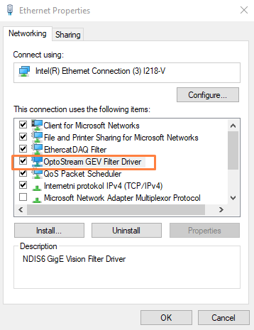
Windows network configuration

Please enter the Control Panel, go to the Network Connections and right-click on the Port, where your Photron camera is connected to. Go to Properties and select the TCP/IPv4 protocol. Depending on the model the default IP address is usually:

  • camera IP: 192.168.0.10 / set computer to 192.168.0.XXX. If a connection cannot be established, please try:
  • camera IP: 192.168.10.0 / set computer to 192.168.10.XXX

The subnet is always 255.255.255.0. This is the default for the currently available cameras. Please refer to the Photron camera manual for further information about the default IP address. Please enter

Network connection settingsImage 82: Network connection settings


Camera IP reset (factory default)

In case you have troubles connecting to the camera, you can try to set it to factory default by the following routine:

  • Press and hold the RESET switch at the camera’s backside.
  • All of the LEDs on the camera's back sidelight, then they turn off sequentially from right to left. In the end, all LEDs together blink twice, then stay on. This takes several seconds, hold the button pressed all the time.
  • Then reboot the camera. The IP address is reset to the factory setting.

Photron FASTCAM Viewer

For checking the network connection (and changing the camera settings), you can use the previously installed Photron FASTCAM Viewer to get a live picture. Please enter the IP address mask as shown above, then click Detect, an auto-search will be performed. Alternatively, click File / Camera open.

Photron Fastcam ViewerImage 83: Photron Fastcam Viewer


Camera TRIG_TTL_OUT pulse duration

When using the Start on Dewesoft trigger option inside Dewesoft, Dewesoft does the synchronization based on the first frame captured by the camera. In the Photron FASTCAM Viewer, please go to Camera Option and increase the pulse output time from 100 nsec (default) to 100 usec, in order to guarantee a proper triggering under any circumstances.

Camera pulse settingsImage 84: TRIG_TTL_OUT setup in PFV


Setup in Dewesoft

Photron.ini file

During installation, we have copied Photron.ini into the Dewesoft X Addons folder (e.g. C:\DewesoftX\X3\Addons64\). This file contains the interface type and IP address of the camera, please set it accordingly.

Photron.ini fileImage 85: Photron.ini file


Enabling the camera

In Dewesoft X go to Settings / Settings / Devices, click the add button and add the Photron FastCam.

Enable the camera in DewesoftImage 86: Enable the camera in Dewesoft


The Photron FastCam camera is successfully found.

Camera successfully foundImage 87: Camera successfully found


When you click on the camera, you should be able to see the model and it's IP address.

Trigger setup

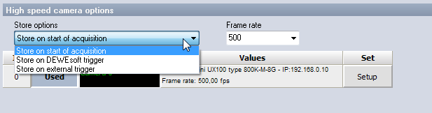
There are three different types of camera trigger:

Store trigger optionsImage 88: Store trigger options


Store on Dewesoft trigger

Store on Dewesoft triggerImage 89: Store on Dewesoft trigger


This is the most commonly used wiring. The software triggers even on complex trigger conditions on analog input, and sends the start impulse over Ethernet. The camera sends a pulse, when the first frame is recorded, this is measured back with the very accurate Dewesoft super-counters (102 MHz timebase) for synchronization.

Store on external trigger

Store on external triggerImage 90: Store on an external trigger


If the camera is triggered with an external trigger, then the same signal can also be used for synchronization.

Store on start of acquisition

The camera will start with the beginning of data recording (streaming). This is of less practical usage, because depending on the framerate, measurement duration and camera onboard memory, the acquisition time is limited.

Store on Dewesoft trigger - example

For connection example, we want to acquire both analog and video data of a hit of an accelerometer with the fingertip.

The analog input sampling rate we set to 200 kS/s (this does not affect the 102 MHz counter sampling rate).


Image 91: Set the analog input channel on used 


We enter the channel setup to get a preview of the signal and check the appropriate trigger level. In the picture below, there is an example of a signal when knocking with a finger on the sensor.


Image 92: Preview the signal in channel settings 


If the Counter section is not visible in the first place, please add them with the plus button from the top. The Counter is set to Event Counting, Basic Event Counting by default, which is ok. Please enable the button on the left of e.g. CNT2/IN0.


Image 95: Counters 


The trigger setup looks like shown below. We select fast on trigger, rising edge with a level of 1g. The pre-time is 100ms, post time 500ms. Dewesoft supports complex trigger conditions, such as simple edge, filtered edge, window, pulse width, slope, delta amplitude, as well as any logical combination on any analog / digital / math channel.


Image 94: Set storing type on fast on trigger
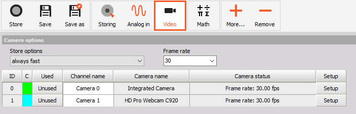

Camera setup

In the video setup, you can see all available cameras. Set the camera to Used, then enter the Setup.

The screen on the next page shows the Trigger setup and the Camera settings, as well as a live preview for adjusting the setup (focus, light source, etc).

Here you can set Resolution, Frame rate, Shutter speed and Sensor gain (if the camera supports hardware sensor gain) parameters. You can also calibrate the camera sensor here. The options depend on the camera model in use and also from each other. For example, if you increase the frame rate, the shutter time will be limited.

The camera settings are applied to the camera as soon as something is changed, so the preview is always up to date with current settings.


Image 95: Camera setup 


Please select the Counter and adjust the level to 0.5, as this is a digital channel (0 to 1). When the camera is started over Ethernet, depending on system load and operating system there will be a delay to the storing trigger. This is usually around 50...100ms (in the example below around 70ms, red line). Therefore, we have to set the camera buffer a little bit higher to capture the whole time window.

Image 96: Trigger explanation


Camera sensor calibration

Each camera comes with two sensor calibration files. Here is an example of how the calibration files are named (e.g. for FastCam 1024 PCI):

  • PixelGainData_Default_1024PCI_1455_0009_0164.gdf
  • shadingdata_1024pci_1455_0009_0164.gdf

If you copy these files from the Photron CD to Dewesoft Addons folder, they will be used automatically. Files are optimized for 1000 fps frame rate and picture will not be optimal when other frame rates are selected. If you do not have these files or factory calibration data is not satisfying or for any other reason the picture is grainy and/or contains fixed shading pattern, you have to calibrate the sensor to get a better picture. You can do that by selecting Calibrate camera sensor from Custom setup and press the Set button. The Calibrate camera window will pop up. Just follow the instructions (Close camera lens and then press OK) and the sensor will get calibrated.


Image 97: Camera calibration  


In the picture below, there is a picture from the camera before (left) and after (right) calibration.

Right picture shows better visibility after calibration in comparison to the first oneImage 98: Right picture shows better visibility after calibration in comparison to the first one


Video download

After the measurement, Dewesoft will show the whole recorded video data. You can navigate without noticeable delay, however, it is only accessing the camera onboard memory. If you have verified the data to be good, you can finally download the video file to the computer. This can take from minutes to hours, depending on the file size.

Example data file

The example below shows the explosion of the firecracker.

Image 99: Image shows the explosion of the firecracker


Frequently asked questions

Camera not detected in PFV

Camera model type not checked in PFV device list:

Image 100: PDV


In Photron FASTCAM Viewer, go to Configuration and select all camera models from the Device List. Now it will search for all of them.

Try connecting multiple times

Sometimes when connecting with PFV, the camera is not found in the first place. Please try again several times.

Network troubles

Disable Windows firewall, disable anti-virus, check IP, reset the camera to factory defaults.