Advanced custom plugin development in C++

Do you have a device and want to insert the data into the Dewesoft on your own? This pro tutorial will teach you how to smooth the signals, minimise the clock drift, and how to make your device the clock provider. By finishing this course you will be a step closer to becoming the plugin master.

Dewesoft, as known today can be used in many interesting ways like measuring the room temperature if digital thermometer is attached, or get the sound intensity from your instrument. Or, perhaps you would like to watch a video of stars from your couch while the camera is doing all the work? Or do you have any other DAQ device and want to insert its data into the Dewesoft? The second Pro Tutorial about C++ plugin development will teach you how to do just that! 

Well, in this Pro Tutorial we will not be looking at the stars but we will teach you how to write C++ plugin so you will be able to do that on your own. For that reason we will use a simple simulator, which will be used as an actual DAQ device. After reading this Pro Tutorial, feel free to replace the simulator with any DAQ device and do whatever you want with its data.

Also, keep in mind that this is the second Pro Tutorial about C++ plugin Development. Before continuing it is recommended to read and understand the first Pro Tutorial about C++ plugin development which is mostly focused on how to create your own user interface, how to save and load XML settings, setting the input and output channels as well as reading from them, etc., by creating your very own latch math module.

In this Pro Tutorial, we will cover different ways of reading and inserting the data from (simulated) devices to Dewesoft. We will do this by simulating a few of the most widely used modes: 

  • Basic mode 
  • SoftSync mode
  • Clock provider mode

When using the above-mentioned modes, Dewesoft will help you by providing already existing classes and functions. By using those classes you will be able to insert device data into Dewesoft in a short manner of time.

The example of the plugin used in this Pro Tutorial can be found in the Daq_Plugin folder.

When we run the plugin we have to manually add it to Dewesoft. We do this by clicking the Settings > Devices, then pressing the button and in the list that appears we choose the Test DAQ plugin.


Image 1: Under settings add the Test DAQ Plugin 


Make sure your chosen Operation mode is Real measurement.


It is hard to follow the code flow if all the code is written in one unit. This is the reason why we created different classes whose header and definition files can be found in the utils folder

The purpose of this section is to show the benefits of object-oriented programming. Details about each mode can be found in the following pages and are currently not important.

BaseDeviceMode class

This is our base class, classes that follow will inherit from it. It contains all the functions which we need to simulate different modes. Some functions are virtual (that means that function in the base class will be re-defined in child classes) because different modes work differently and require something that is not needed in other modes (eg. Start function). Other functions, which are not virtual, are common to all modes, therefore they do not need to be re-defined in child classes (eg. GetTime function).

A virtual function can be recognized by keyword virtual before function prototype. We will now show an example of re-defining Start function inside base class and child class SoftSync

virtual Device::HANDLE Start(Device device);

The definition for Start function inside SimulatorModeBase.cpp looks like this: 

Device::HANDLE BaseDeviceMode::Start(Device device)
{
    Device::HANDLE handle = device.Connect();
    Device::AcquisitionStart(handle);    
    return handle;
}

The return value of device.Connect() is a handle, which is used as a parameter to every function in Device class. 


  1. Basic mode

Represents a child class of BaseDeviceMode, virtual methods are re-defined here. The definition for Start function in BaseDeviceMode class is enough so there is no need to re-define it in BasicMode class.

Since Basic mode is "just basic", we will simplify it as much as possible. This is why we re-define the GetData function to only insert one sample per block of data. This sample will be the first sample in the data vector. We do this by saving the first value to a new variable, clearing the data vector and then inserting the variable back into the vector. We need to return a vector with our sample and not just the sample because of the definition of the GetData function in BaseDeviceMode class. 

std::vector<double> BasicMode::GetData(int numberOfsamples)
{
    std::vector<double> data;
    DaqSimulator::Device::GetData(deviceHandler, &data);
    if (!data.empty())
        data.resize(1);        
    return data;
}
Details about this mode can be found on the Basic mode page.

  1. SoftSync Mode

Represents a child class of BaseDeviceMode, virtual methods are re-defined here.

Since SoftSync mode needs some extra initialization for private members, we will do this in the Start function. Therefore, we will have to re-define it. The redefinition starts in the header file with the function prototype by keyword override after the parentheses, that indicate the end of arguments. Override ensures that the function is virtual and is overriding a virtual function from a base class. An example of a re-defined Start function inside SoftSyncMode.h can be seen below.

Device::HANDLE Start(Device device) override

Start function definition inside SoftSyncMode.cpp:

Device::HANDLE SoftSyncMode::Start(Device device)
{
    HANDLE deviceHandler = BaseDeviceMode::Start(device);
    srand(time(NULL));
    softSync.initiate();
    softSync.setDeviceRate(1);

    startTime = Device::GetSystemTime(deviceHandler);
    double slaveTime = Device::GetSystemTime(deviceHandler) - startTime;
    lastSyncingTime = std::chrono::high_resolution_clock::now();
    return deviceHandler;
}
The main purpose of this example code is to emphasize the re-definition process of the BaseDeviceMode::Start function. The code (initialization of SoftSync class members) inside function definition is currently not important and will be explained throughout the tutorial.
Details about this mode can be found on the SoftSync page.

  1. ClockProvider mode

Represents child class of BaseDeviceMode, virtual methods are re-defined here. 

Although the ClockProvider mode is the most complex, the Start function defined inside the base class will be enough. The ClockProvider mode is further split into two sub-modes, one is synchronous and the other one is asynchronous clock provider mode. The ClockProvider class will be used for both sub-modes. The only differences between the two are how the data is inserted into the output channel and providing the clock for other plugins, therefore, we can use the same class code for both modes.

Details about this mode can be found on the ClockProvider page.

In the future, the phrase device will stand for our simulator.

Our device is found in Settings -> Devices -> Test DAQ plugin. When the plugin is first started, we have to specify the Time source for our plugin. Lets set the Time source in the drop-down menu to Test DAQ Plugin. That means that our plugin will be the clock provider.

Image 2: Set the Test DAQ Plugin as the Time source in Local system settings 


If we now click on the Test DAQ plugin node, we should be able to only pick among Clock provider synchronous and Clock provider asynchronous mode. 

But if we pick any other option from the drop-down menu, we can only use Slave modes. Therefore, we can only choose between SoftSync and Basic mode.

Image 3: Set Test DAQ Plugin parameters in Device settings 


The settings of the Test DAQ plugin are:

  • Device sample rate means a reduced number of discrete-time signals which we get from a continuous-time signal. In other words, it describes the number of samples which will be returned every second. It is measured in Hertz [Hz]. So if we set the Device sample rate to 50Hz, a new sample is available every 20 milliseconds, but if we set it to 250Hz, a new sample is available every 4 milliseconds. We usually do not ask for a sample every time a new one is available, but we ask few times a second and if there is more than one sample available, we have to deal with a block of samples. So if we have a sample rate of 250Hz, and ask for samples every 25 milliseconds, we will receive a block of 6 samples. You can later (when performing calculations) decide what to do with those samples.

  • Synchronization type represents the mode, in which we are currently performing the calculations. Current device mode is a user-settable parameter and can be changed on-the-fly. To keep an eye on the current mode, we will use a variable of the Enum type. Its value can therefore only be set to Basic, SoftSync, Clock provider sync, and Clock provider async. A quick and rough explanation of modes is as follows:
    • Basic mode - Only outputs the first sample from the block of samples, the clock is provided by Dewesoft
    • SoftSync mode - Outputs the entire block of samples, the clock is provided by the device and is synced with the master clock every 200ms
    • Clock provider - Outputs the entire block of samples, the clock is provided by the device which is also the master clock (meaning no time synchronization with Dewesoft). If using ClockProviderSync mode output channel is Synchronous, and Asynchronous otherwise.

Since we are using a simulator that runs in near perfect conditions, we also define an extra variable, Fuzz factor. With this we can simulate the errors in timestamps that arise in real devices:

  • Fuzz factor is only applied when calculations are performed in SoftSync mode. Its values can be set between 0 and 20. Fuzz factor is the difference (in milliseconds) between real device time and the time that is actually returned.
    • When the fuzz factor is set to 0, the device returns its real device time.
    • When the fuzz factor is set to 20, the device returns real device time plus a number between -20 and 20. This number represents the deviance in milliseconds and is determined randomly. As you can imagine, device timestamps will be corrupted and SoftSync will reduce corruption to a bare minimum.
Settings above are automatically saved into the XML file when entered/changed and loaded when the plugin is started, so they do not have to be re-entered every time. 

In this tutorial, we will not cover things like storing and loading XML settings, the creation of the user interface and usage of user interface components. All those things can be found in the Basic custom plugin development in C++ Pro Tutorial.

The code for the simulator can be found in DaqDeviceSimulator project. Function prototypes can be found inside DaqDeviceSimulator.h file and are described below. 

  • Devices in real life usually require that we connect them before we start using them and disconnect when we stop. Connect function will return the handle to the device and the Disconnect function will delete it.
HANDLE Connect();
void Disconnect(HANDLE device);
  • All devices have a name and port number in the following code we can see how we read them.
std::string GetDeviceName(HANDLE device);
int GetDevicePort(HANDLE device);
  • Reading the acquisition sample rate of the device can be done as seen in the code below. We usually use it when setting the expected sample rate of the output channel.
int GetDeviceSampleRate(HANDLE device);
  • Setting the acquisition sample rate of the device is done as follows.
void SetDeviceSampleRate(HANDLE device, int sampleRate);
  • Functions for reading the data from the device can be seen below. GetData returns the block of data values, GetTime returns the block of timestamps when samples were acquired.
int GetData(HANDLE device, void* data);
void GetTime(HANDLE device, void* time, int numberOfSamples); 
  • To start and stop the acquisition we call the next two functions.
void AcquisitionStart(HANDLE device);
void AcquisitionStop(HANDLE device);
  • Reading the precise device time can be done as seen below. If Fuzz factor is more than 0, it returns time with Fuzz factor taken into account.
double GetSystemTime(HANDLE device, double fuzzFactor=0);


All function definitions can be found in DaqSimulator.cpp file.

Basic mode is the easiest one (to understand and use) among all of them. It is only used when conditions are perfect. In real life, there are many things that prevent perfect conditions, like device failures, lost samples, jitter when asking the device for device time, also clock drift should be taken into account and many other things. So if those mistakes are somehow eliminated, it is safe to use this mode.

To use the Basic mode, we have to go to Settings -> Devices tab -> Test DAQ Plugin and under Synchronization Type choose an item with Basic mode caption. The sample rate in Basic mode is determined by the Device Sample Rate combo box.

Image 4: Set the Basic mode as the synchronization type 


In Basic mode, we only need to override the base function GetData. Remember that in this mode we decided to only keep the first sample in a block of data. The decision was made to emphasize the simplicity of Basic mode, and because (in general) asynchronous channels should have fewer samples than synchronous channels. Therefore overridden function in BasicMode.cpp should look like this.

std::vector<double> BasicMode::GetData(int numberOfsamples)
{
    std::vector<double> data;
    DaqSimulator::Device::GetData(deviceHandler, &data);
    if (!data.empty())
        data.resize(1);        
    return data;
}

Now we insert a sample in the output channel. Since in basic mode we use Dewesoft's clock, we do not need to ask the device for the time.

double DSTime = app->MasterClock->GetCurrentTime();
std::vector<double> data = deviceMode->GetData();
if (!data.empty())
    outputChannel->AddAsyncDoubleSample(data[0], DSTime);

When asking the device for its time there is some delay. Therefore, you will never really know if the returned device time is precise. This is the reason why we will use a SoftSync mode. Because our device is actually a simulator, meaning data that it returns is near flawless, we have implemented a fuzz factor, which changes the time that is returned from the device (to get the device time we use GetSystemTime() function).

In order to use SoftSync mode PC Clock needs to be selected as the Clock source. 

Image 5: In order to use SoftSync, select PC Clock as the Time source 

When Clock source is set to PC Clock, we have to go to Settings -> Devices tab ->Test DAQ Plugin and under "Synchronization Type" choose an item with "SoftSync mode" caption. The sample rate in SoftSync mode is determined by the value you choose in the "Device Sample Rate" combo box. 

An example of corrupted data can be seen in the picture below.

Image 6: Corrupted data 

Here we will see the real value of the SoftSync algorithm. It can be used for many different things, like smoothing the signal and dealing with clock drift, which appears because the device clock does not run at exactly the same rate as the reference clock. We should also mention, that in SoftSync mode, the reference clock is still the Dewesoft clock (the same as in Basic mode). In the further reading the term Master clock will refer to the reference clock, and the other clock, which uses the reference clock to be synchronized, will be called the Slave clock. 

Although the sine wave is pretty obvious in the picture above, the signal itself is pretty distorted. We will try to make it more continuous by using class SoftSyncAlgorithm which is a part of CommonLib, and its functions are declared there as well. To use CommonLib you have to build it first. More information about the building is available in README.md inside CommonLib folder. We recommend that you set a system variable called COMMON_LIB_ROOT to the directory, where your commonLib was built. To use SoftSyncAlgorithm class, we have to include its header file in include Directories and add Library Directories. This is done under TestDaqPlugin properties -> Configuration properties -> VC++ Directories.

-
Image 7: To use SoftSyncAlgorithm class, we have to include its header file in include Directories and add Library Directories. This is done under TestDaqPlugin properties -> Configuration properties -> VC++ Directories.


Now all we are left to do is specify the name of .lib file in TestDaqPlugin properties -> Linker -> Input -> Additional dependencies.


Image 8: Specify the name of .lib file in TestDaqPlugin properties -> Linker -> Input -> Additional dependencies 


When everything is done, and SoftSyncAlgorithm is finally accessible we can start using it. Code part of SoftSync can be found on the following page.

When everything is set and the SoftSyncAlgorithm is finally accessible, we can start with the coding. You can follow along by opening utils/SoftSyncMode.h and .cpp files. To begin with, we need to include the header files into our code by adding the following include to our file

#include <commonlib/synchronization/softsyncalgorithm.h>
using namespace Dewesoft::Utils::Synchronization;

Next, we will create a new private member in SoftSyncMode class called softSync.

private:
       SoftSyncAlgorithm softSync; 

This member needs some extra initialization, which is done in SoftSyncMode::Start function. We have to override BaseDeviceMode::Start function, since base initialization will not be enough. 

public:
    Device::HANDLE Start(Device device) override;

Because basic initialization is still necessary, we will call BaseDeviceMode::Start function first. Then we have to initiate the SoftSync member using softSync.initiate();

It is also a good idea to not sync master and slave time whenever we get new samples, because syncing on every getData would cause our signal to not be continuous. In our case, we will sync master and slave clock every 200 milliseconds. For that reason, we also set the start values to members startTime and lastSyncingTime so we will know when 200 milliseconds have passed. 

SoftSync Start function should now look like this.

Device::HANDLE SoftSyncMode::Start(Device device)
{
    HANDLE deviceHandler = BaseDeviceMode::Start(device);

    softSync.initiate();
    softSync.setDeviceRate(1);

    ResetValues();

    return deviceHandler;
}

Besides Start function, it is important to pay attention to the following functions: 

  • TrySynchronizingClocks(masterTime)
  • GetMasterTime(slaveTime) 

TrySynchronizingClocks is used for syncing master and slave clock. This is done by executing the following statement   softSync.synchronizeClocks(masterClock, slaveClock);, where masterClock is time provided by Dewesoft and slaveClock is time provided by our device. How synchronizeClocks works is by calculating the difference between the slave clock and the master clock. Using this difference it will later adjust the slave clock. This is the function we will call every 200 milliseconds.

GetMasterTime is a wrapper function which calls softSync.masterTimeAt(double time);. This function should be called for every timestamp which was returned from the device, before inserting it into the output channel. What this function does is it takes the difference which was calculated in TrySynchronizingClocks function and adds it to the timestamp value. The return value is the actual time when a specific sample value should be inserted into the output channel.

The TrySynchronizingClocks function needs to be called before calling the GetMasterTime function.

In the picture below you can see the same starting signal, which was processed by SoftSync and is now more continuous compared to the one without SoftSync. If you look closely, you can see that every once in awhile a signal has a small spike. This happens on approximately 200 milliseconds. This is the time when the TrySynchronizingClocks function is called. 


Image 9: Signal processed by SoftSync which is more continuous compared to the one from the image 6


In the SoftSync section, we used Dewesoft's clock as the master clock and the device clock as the slave clock, so we changed the timestamps of our samples according to the master clock. But in this mode, our device will be the clock provider, meaning that the device will be the master clock. When in Clock provider mode, our output channel can be synchronous or asynchronous type. First, we will describe the simpler one, which is the asynchronous type. 

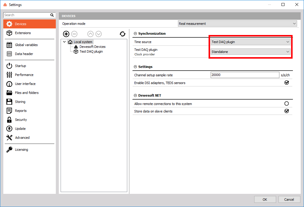
To use a Clock provider mode, we have to specify that we are the clock provider. We do this by selecting the Test DAQ Plugin item from the drop-down Time source menu. 


Image 10: In settings set the Test DAQ plugin as the Time source 


We can later go to Settings > Devices tab > Test DAQ Plugin and under Synchronization Type choose Clock provider sync or Clock provider async. The sample rate in Clock provider mode is NOT determined by the value you choose in the Device Sample Rate combo box, therefore, it does not matter which value is selected. The sample rate is the same as the Dynamic acquisition rate, which is set in Ch. Setup under Analog in tab.


Asynchronous clock provider mode

If your device is intended to be the clock provider, Dewesoft needs to somehow be notified. This is done in plugin_impl.h file using STDMETHOD(raw_ProvidesClock(VARIANT_BOOL * Value)); function. As you can see in the function prototype, the argument Value is passed by reference. You should set its value to true if you want your plugin to be the master clock, or to false otherwise.

Function definition should, therefore, look like this.

STDMETHODIMP_(HRESULT __stdcall) Plugin::raw_ProvidesClock(VARIANT_BOOL * Value)
{
    if(bridge.providesClock())    
        *Value = TRUE;
    else *Value = FALSE;
    return S_OK;
 }

Now that we have specified that our plugin will provide the clock, we have to specify the time for other plugins whenever they ask for it. We do this by keeping track of number of samples which were outputted into the output channel. We then calculate the time as a function of number of samples outputted and the device sample rate inside plugin_impl.h file using STDMETHOD(raw_OnGetClock(long * clockLow, long * clockHigh)); function:

void DewesoftBridge::onGetClock(long * clockLow, long * clockHigh)
{
    int64_t samples;
    if (OtherPluginsAskingForClock(*clockLow))
        samples = EvaluatedSamplesCount();        
    else
        samples = acquiredSamplesFromDevice;

    *clockLow = getLowest32Bits(samples);
    *clockHigh = getHighest32Bits(samples);
}

The getLowest32Bits and getHighest32Bits functions use the number of samples acquired and split them into two 32-bit numbers, representing the lowest and highest 32 bits of the actual count. Mentioned functions are using 

long getLowest32Bits(int64_t samples)
{
    return samples & 0xffffffff;
}

long getHighest32Bits(int64_t samples)
{
    return (samples >> 32);
}

Now all that we have to do is insert the samples to the output channel. This is done the same way as it is done in the SoftSync mode, but we do not have to modify the time which was returned from the device. Therefore we just insert sample values and sample timestamps directly into the output channel using the following lines of code.

for (size_t i = 0; i < data.size(); i++)
{
    outputChannel->AddAsyncDoubleSample(data[i], time[i]); 
    acquiredSamples++;
} 

When using the asynchronous channel, the number of samples that are inserted into the output channel is determined by the programmer. In the example code above we inserted a whole block of data into the output channel whenever we received new ones. That is why we added the following line of code, acquiredSamples++; so our DewesoftBridge::onGetClock function will provide the correct time whenever asked for time (as already mentioned, when your plugin is clock provider, you provide a clock by specifying the number of inserted samples).


Synchronous Clock provider

Whenever we are using Synchronous Clock provider mode, we have to set our output channel to be synchronous. It is done in Dewesoft_bridge.h inside STDMETHODIMP onPreinitiate(); event. If you can not find this function, you should create your own implementation. It is done in plugin_impl.cpp file inside STDMETHODIMP Plugin::raw_OnEvent(enum EventIDs eventID, VARIANT inParam, VARIANT* outParam) function. You have to catch a new event called evPreInitiate and add it to the switch-case block. Example code looks like this:

STDMETHODIMP Plugin::raw_OnEvent(enum EventIDs eventID, VARIANT inParam, VARIANT* outParam)
{
    switch (eventID)
    {
        //other events
        case evPreInitiate:
            returnValue = eventPreinitiate();
            break; 
    }
}

plugin_impl.h

STDMETHODIMP eventPreinitiate();

plugin_impl.cpp

STDMETHODIMP Plugin::eventPreinitiate()
{
    bridge.onPreinitiate();
    return S_OK;
}

dewesoft_bridge.h

STDMETHODIMP onPreinitiate();

dewesoft_bridge.cpp

STDMETHODIMP_(HRESULT __stdcall) DewesoftBridge::onPreinitiate()
{
    if (mode == ClockProviderSync) 
        outputChannel->SetAsync(false); // check with breakpoints if it is ever set back to async
    return S_OK;
}

When your device is meant to provide clock and performs in synchronous mode we have to specify it by using the same code as we did in asynchronous clock provider (pay attention to STDMETHOD(raw_ProvidesClock(VARIANT_BOOL * Value)) function).

As we have already mentioned, when in Asynchronous mode, we can decide how many samples we want to insert into the output channel. Well, this is not possible when in Synchronous mode because we must insert an exact number of samples. To get this exact number, we have to call getCurrentSampleCount function, which returns the number of all samples that could have been added since the start of the measurement, and subtract the number of samples we already outputted. That is why we need to increment the value of insertedSamples variable whenever we output data into the output channel.

int64_t samplesToInsert = getCurrentSampleCount() - insertedSamples;
At this point, we have modified the Device::GetData function to provide us with the exact number of samples. It now looks like this: int GetData(HANDLE device, void* data, int numberOfsamples = 0);. By adding , int numberOfsamples = 0 parameter, we will not change Device::GetData function calls from other modes.

But there are a few things which we need to take into the account when we are using the device to provide us the data. In this example, we modified the Device::GetData function to return the exact number of samples which we need to insert. In this case, we just insert all the samples into the output channel. We do this using the following code.

int64_t samplesToInsert = getCurrentSampleCount() - insertedSamples;
 for (int i = 0; i < samplesToInsert; i++) {
      outputChannel->AddDoubleSample(data[i]);
      insertedSamples++;            
 }

But what if the device returns fewer samples than the output channel needs? Or what if the device returns more samples than needed?

In the first scenario (numberOfSamples < samplesToInsert), we have to set the calcDelay property of the output channel to the number of samples that are missing. Example of setting the calcDelay:  outputChannel->CalcDelay = samplesToInsert - data.size();

In the second scenario (numberOfSamples > samplesToInsert), we have to store the extra samples, so they will be ready to be inserted in the next onGetData function call. To store the extra samples we will generate a new class member which will hold all un-inserted data. 

Function void onGetClock(long* clockLow, long* clockHigh); should remain the same as it was when in Asynchronous clock provider mode. In asynchronous we were counting a number of samples we inserted, while in synchronous, we are calculating samples by multiplying time (since the start of the measurement) with device sample rate. 

double secondsPassed = (std::chrono::high_resolution_clock::now() - startTime).count() * 1e-9;
acquiredSamples = secondsPassed * Device::GetDeviceSampleRate(SineWaveGenerator);