C++ Signal Processing Plugin

Wouldn't it be great to be able to extend Dewesoft on your own? With a little help of C++ and our new feature C++ Processing Plugin is now possible developing your own plugins, testing new things whenever and wherever you want, setting your own boundaries and designing custom GUI. Finish this course and start creating custom plugins for processing your data.

Extending Dewesoft in the past was a daunting task. Writing a proper plugin for Dewesoft required extensive knowledge of how the software operated under the hood.

C++ Script demonstrated that it really doesn't need to be that way, that writing plugins could (and should) be an easy process. The problem with the "legacy" plugin system was that it was written too generically. It gave the programmer great power over Dewesoft, but it was really difficult to write even a trivial plugin from scratch. 

Processing plugin tries to fix this. It uses Dewesoft's DCOM interface to access its internals, but abstracts the interaction away from the programmer (almost) completely. The end result is that while you can directly control Dewesoft as you would with more bare-bones plugin system, you can write the plugin almost as if you were writing C++ Script - except with much more powerful debugging tools C++ Script could ever offer. You can take arbitrarily many input channels, process the data using modern C++, output the results into output channels, change Dewesoft settings, and much much more!

This pro training builds on top of C++ Script's pro training, so it is advisable to read that first.

C++ Processing Plugin also allows you to create your very own user interface which is, together with your C++ code, compiled into an external library and automatically recognised and loaded by Dewesoft. This is why your plugin can be easily exported and imported for use on other computers.


In order to start using C++ Processing Plugin, you must have Visual Studio IDE installed on your system. Some of the reasons we have chosen Visual Studio are its combination of powerful developer tooling and debugging.

You can download the DewesoftX Processing Plugin Template from the Dewesoft webpage under Support > Downloads > Developers > C++ Plugin. Note that you have to be logged in to access the C++ Plugin section. After downloading, just double-click the file and VSIX installer will guide you through the installation process. Once Visual Studio Development tool is installed you will be able to download the Dewesoft plugin template using the New project window and selecting the DewesoftX Processing plugin template. 


To develop processing plugins you need to use the latest development version of Dewesoft X software installed on your development PC. The resulting processing plugins can be used with older versions of Dewesoft X, but they must be developed against development version.

In this pro training we will again be recreating latch math, as we did in C++ Script training, so the C++ Script pro training and its understanding is the prerequisite for this tutorial and we will only build on the knowledge. This is so that the parallels between C++ Script and Processing plugin are as apparent as possible. So, to follow along, we recommend that you first read that tutorial available at Dewesoft > Training > PRO Training > Develop > C++ Script, and prepare the same setup as created in its Example: Latch math chapter.

Powered by Froala Editor

To create a new C++ Processing Plugin we click the Project button in File tab -> New -> Project. We select the DewesoftX C++ Processing Plugin Template as our template. After clicking the Ok button a wizard window will appear to guide us through the creation of the plugin.


Since your plugin will be integrated inside Dewesoft, it needs to know Dewesoft's location. We can define the location by ourselves and the installer will create DEWESOFT_EXE_X86 (for 32-bit Dewesoft) and DEWESOFT_EXE_X64 (for 64-bit Dewesoft) system variables for us. In that case, Visual Studio will have to be restarted so it will update its used environmental variables state. 

Once those system variables are set, installer will automatically find those fields for you and you will not have to specify the location for further usages.

If we want to set those variables ourselves, we can do this using System properties window (it can be found pressing Windows key and searching for Edit the system environment variables), and under advanced tab clicking the Environment variables. 

If you only have the 64-bit (or 32-bit) version of Dewesoft on your computer, you will only be able to create 64-bit (or 32-bit) plugins.

After clicking the Next button the following window appears which is used to set Plugin information such as plugin name, its ownership, and version.

Image 4: Set the Plugin information such as plugin name, its ownership, and version 
  • Plugin name - The name that will be seen in Dewesoft.
  • Description - Short description of your plugin.
  • Vendor - Company that created the plugin.
  • Copyright - Owner of the plugin.
  • Major version - Sets the initial major version. The value should change when a breaking change occurs (it's incompatible with previous versions).
  • Minor version - Sets the initial minor version. The value should change when new features and bug fixes are added without breaking compatibility.
  • Release version - Sets the initial release version. The value should change if the new changes contain only bugfixes.

All fields are optional except for the Plugin name, and they can all be modified later from the code.

After clicking the Next button a final window appears. This window is used to set your Base class name. It is used as a prefix for class and project name. When the Base class name is set, we can click the Finish button and the wizard will generate the plugin template based on your choices. 

The Solution name is the name of the solution created by the Visual Studio.
The Plugin name is the name of the plugin as seen in Dewesoft.
The Base class name is the name used for Plugin's classes, and has to be a valid C++ name.

Once the plugin is created and you stumble upon Error MSB8036: The Windows SDK version sdk_version was not found. You should retarget your solution to use the one you have installed. You can do this by right clicking on your solution node in Solution explorer and selecting Retarget solution.

Once the Retarget solution window is opened, you can select "Latest installed version" item.

Structure of the solution

When a new C++ Processing Plugin project is created, the wizard will create the basic files and project structure needed for development. In the picture below you can see the structure of a project in a tree view with collapsed items. In our case, LatchMath refers to text which was used as the Base class name.

Image 6: New C++ Processing Plugin is created 


  • LatchMathPlugin - The actual plugin implementation
  • LatchMathPluginTest - Solution for writing unit tests for LatchMathPlugin. 
  • gtest - Google test library, required by LatchMathPluginTest for unit testing your plugin. This project should not be modified. 

As mentioned before, our plugin implementation is inside the LatchMathPlugin project. It contains files for writing the UI of the plugin, for writing the main code, and dewesoft_internal folder with methods your plugin is going to use behind the scenes for interacting with Dewesoft. In addition you can also see the icon.png file containing the icon used by the plugin. plugin.h and plugin.cpp serve as the entry points for your plugin, and contain the base class with the same name as defined with Base class name. Here we connect the input channels, mount the output channels and write the logic of the plugin, much like we would in C++ Script. We can also set additional properties of the plugin and save the setup variables.

dewesoft_internal folder should not be modified.

The UI folder is split into two additional folders for editing the setup UI and for the settings UI. The setup UI is the one you see when you enter the plugin setup form, and the settings UI can be found by clicking Options -> Settings -> Extensions and locating your plugin. Both setup and settings folders have .xml file for writing the UI, a .h header file for defining the methods and variables and a .cpp file for writing the logic for the UI.

When the solution is built for the first time, we recommend rescanning it (to clear cache). If not, some false positive errors might appear and auto-complete might not work. You can do this by clicking on the Project tab and choosing the Rescan solution from the drop-down list.

When our project is successfully generated, we will be able to extend Dewesoft. But before implementing the logic behind our plugin, let's take a look at how our plugin is integrated into Dewesoft by default. In order to do that, we have to start our program using the shortcut F5 or pressing the Start button in the center of Visual Studio's main toolbar. 

Image 7: Press the start button in the Visual Studio's main toolbar 


Depending on your Visual Studio, you might experience issues trying to run our program, but there is a quick fix for that. From v16.1 Visual Studio 2019 blocks any synchronously autoloaded package from any extension. To stop blocking synchronously autoloaded extensions in Visual Studio, navigate to Tools -> Options -> Extensions and check Allow synchronous autoload of extensions checkbox in the options dialog.


After Dewesoft loads, our plugin can be accessed in Dewesofts main toolbar in Measure mode under Ch. setup -> More... -> Latch math - scalar. As we can see, it already contains some example elements which were automatically added to the user interface. 

Image 8: Access the plugin in Dewesoft's main toolbar in Measure mode under Ch. setup -> More... -> Latch math - scalar 


It is important to keep in mind that C++ uses header files (you can recognize them by the .h extension) in addition to source files. Header files are designed to provide information about your class and are used for declaration of variables and methods, while their initialization is done in the source files with .cpp extension. 

When we first create a new plugin the project LatchMathPlugin also contains an example of a plugin for adding an offset to the input signal. Before writing our own code, we will first remove the sample code as it is not needed for the plugin we will write in this tutorial. 

Our ui/setup/setup_window.h should look like this:

#pragma once
#include "generated/ui/setup/plugin_setup_window.h"
#include "plugin.h"

class LatchMathSetupWindow : public LatchMathSetupWindowBase
{  
  public:    
    virtual void bindEvents() override;    
    virtual void initiate() override;
};

and ui/setup/setup_window.cpp should look like this: 

#include "StdAfx.h"
#include "ui/setup/setup_window.h"

using namespace Dewesoft::MUI;

void LatchMathSetupWindow::bindEvents()
{
}

void LatchMathSetupWindow::initiate()
{
}

Let's also remove everything but the very basics from the ui/setup/setup_window.xml:

<?xml version="1.0" encoding="utf-8"?>
<Window xmlns="https://mui.dewesoft.com/schema/1.1">
</Window>

We will also remove any sample code from the plugin.h and plugin.cpp file. We only keep the methods that will be used later.

The plugin.h file should look like this

#pragma once
#include "interface/plugin_base.h"

enum class OffsetType
{
    Fixed = 0, 
    Dynamic = 1,
};

class LatchMathModule : public Dewesoft::Processing::Api::Advanced::Module
{
  public:
    static void getPluginProperties(PluginProperties& props);

    void configure() override;
    void calculate() override;
   
    void updateSetup(Setup& setup) override;
   
    void connectInputChannels(InputChannelSlots& slots) override;
    void mountChannels(OutputChannels& fixed, OutputChannels& dynamic) override;
};

class LatchMathSharedModule : public Dewesoft::Processing::Api::Advanced::SharedModule
{
};

and the plugin.cpp file should look like this.

#include "StdAfx.h"
#include "plugin.h"

namespace adv = Dewesoft::Processing::Api::Advanced;
using namespace Dewesoft::Utils::Dcom::Utils;

void LatchMathModule::getPluginProperties(PluginProperties& props)
{
    props.name = "Latch math - scalar";
    props.description = "Pro Tutorial example.";
    props.pluginType = PluginType::application;
    props.hasProjectSettings = false;
}

void LatchMathModule::connectInputChannels(InputChannelSlots& slots)
{
}

void LatchMathModule::mountChannels(OutputChannels& fixed, OutputChannels& dynamic)
{
}

void LatchMathModule::configure()
{
}

void LatchMathModule::calculate()
{
}

void LatchMathModule::updateSetup(Setup& setup)
{
}

With these changes we are ready to start writing our latch math plugin.


Let's start by writing the logic of our plugin. This is done by editing plugin.h and plugin.cpp files of the project. Much like in C++ Script, these files contain classes with methods that Dewesoft automatically calls whenever appropriate (e.g. when measuring is started, when measuring is stopped, when setup is saved,...). 


Let's first create the two input channels required by our plugin. Unlike in C++ Script where we were able to just click on the user interface to add the channels, we have to create these "by hand" in Processing plugin. We do this by making changes to the plugin.h and plugin.cpp files. In the plugin.h file we define the two input channels as public variables of the Module class.

class LatchMathModule : public Dewesoft::Processing::Api::Advanced::Module
{
  public:    
    // ...
    ScalarInputChannel criteriaChannelIn;
    ScalarInputChannel inputChannelIn;
};

Note that the types of the channels are ScalarInputChannel, exactly like in C++ Script. This is not by accident. In fact, channels in Processing plugin have very similar interfaces as the ones defined there, so if you are familiar with C++ Script, it shouldn't be such a jump to master Processing plugin channels. 

In the plugin.cpp file we now reserve two input slots (top left panel on the settings window) that will hold our channels and connect them with the variables we just defined. We do this by modifying the connectInputChannels() method:

void LatchMathModule::connectInputChannels(InputChannelSlots& slots)
{
    slots.connectChannel("Input channel", &inputChannelIn, ChannelTimebase::Synchronous);
    slots.connectChannel("Criteria channel", &criteriaChannelIn, ChannelTimebase::Synchronous);
}

With this, we specified that our two input slots will be called "Input channel" and "Criteria channel", and their timebases will be synchronous.

By specifying the type of our input channels as ScalarInputChannel, we have told Dewesoft that we expect our channels to hold scalar values. That is why Dewesoft will automatically filter out all channels that are not scalar when letting the user choose a channel for a particular slot. If our processing plugin only worked with e.g. complex vectors, all we would have to do is set the type of the channel as ComplexVectorInputChannel, and Dewesoft would take care of the rest for us.

The last thing we need to do to get the code to compile is to edit the getPluginProperties() method. Here we can change the general behaviour of our plugin - how many channels it accepts, where in Dewesoft it appears, if it has a settings form or not, etc. For our purposes, the only thing that really matters is the inputSlotsMode property which will allow our plugin to accept multiple inputs.

void LatchMathModule::getPluginProperties(PluginProperties& props)
{
    props.name = "Latch math - scalar";
    props.description = "Pro Tutorial example.";
    props.pluginType = PluginType::application;
    props.hasProjectSettings = false;
    props.inputSlotsMode = InputSlotsMode::multiple;
}

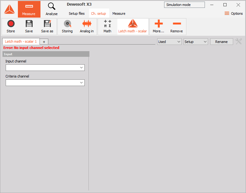
Compile the project and you should be able to find our plugin under "More..." menu. Adding it you can see the two input slots we prepared for our plugin:

Image 9: Compile the project and add your plugin inside More... tab 

Next, let's prepare variables that will control the behaviour of our latch math. We will do this in the plugin.h file where we define the public variables for the criteria limit and for the edge type. We will also create a custom enum for edge type so the code will be more descriptive.

enum edgeTypes
{    
    RisingEdge = 0,    
    FallingEdge = 1
};

//...

class LatchMathModule : public Dewesoft::Processing::Api::Advanced::Module
{
  public:    
    // ...
    double criteriaLimit = 0;    
    edgeTypes edgeType = RisingEdge;
};

mountChannels

Next, let's add some output channels to our plugin. Again, in C++ Script this was done by clicking on the UI, but here we have to do it all by hand. First let's add a variable that will hold our output channel to plugin.h:

class LatchMathModule : public Dewesoft::Processing::Api::Advanced::Module
{  
  public:    
    // ...
    ScalarOutputChannel outputChannel;
};

To actually register the channel with Dewesoft, we use a special method called mountChannels(). Here we set basic channel properties like the name of the channel that is seen by the end-user, the channel index, which should always be unique. The type of value that the channel will output is determined from the definition of the channel in the plugin.h file, and since we defined our channel as ScalarOutputChannel it means that our channel will output scalar values.

We also need to set the timebase of the output channel. We do this by mounting the channel with the mountSyncChannel() function if we want the timebase to be synchronous, mountAsyncChannel() for asynchronous timebase or mountSingleValueChannel() if we want the timebase to be a single value. In our example, the output channel should be of an asynchronous type because we do not know exactly when a new sample will be added. 

As you can see from the code snippet below we can mount channel as fixed or dynamic channel. The difference between the two is that Fixed must always contain a constant number of channels, while Dynamic may contain a different number of channels every time the mountChannel() method is called.

void LatchMathModule::mountChannels(OutputChannels& fixed, OutputChannels& dynamic)
{
    fixed.mountAsyncChannel("Latch", 0, &outputChannel);
}

configure

The configure() method gets called every time before the measurement is started. This is the place to set the final settings dependent on and regarding channels. 

Here we set the output channels' expectedAsyncRate and can also change the output channels' name, unit and description.

Another important thing to be set here is the properties of the resampler. 

void LatchMathModule::configure()
{
    resampler.blockSizeInSamples = 1;
    resampler.samplingRate = ResamplerSamplingRate::Synchronous;
    resampler.futureSamplesRequiredForCalculation = 1;

    outputChannel.setExpectedAsyncRate(5);
}

To make sense of the code above we will take a detour and take a closer look at the resampler and its properties:


resampler

The C++ Processing Plugin works so that all the input channels of the plugin get resampled to the same sample rate, which means that all the input channels have samples at the same timestamps. In C++ Script this is done automatically, with every input channel getting resampled to the timebase of the first assigned input channel. In Processing plugin we get a lot more control over the behaviour of the resampler.

The sampling rate can be: 

  • Synchronous  - all the samples will be spaced equidistantly based on the acquisition sample rate;
  • SingleValue - the input channels only have one sample as an input, and the calculate() function will get called once every couple hundred milliseconds; and
  • AsynchronousSingleMaster - the samples get resampled to the asynchronous rate of the master channel. To set the master channel we need to call setMasterChannel() function like so: resampler.setMasterChannel(&inputChannelIn);

We also need to set the number of samples we receive in every calculate() call. This is set with the blockSizeInSamples property, if we choose it to be 1 then the calculation will be sample-based and we only receive one sample per calculate() call, but if we set it higher then we receive a block of samples every time.

Sometimes we need access to previous or future samples in order to correctly process our signal, in this case, we use the futureSamplesRequiredForCalculation or pastSamplesRequiredForCalculation which allows us to access these samples. 

calculate

This method is called repeatedly during Measure mode. Here we can safely read from and write to the channels. In this method, we add the actual logic for our plugin:

void LatchMathModule::calculate()
{
    float currentSampleCriteriaChannel = criteriaChannelIn.getScalar(0);
    float nextSampleCriteriaChannel = criteriaChannelIn.getScalar(1);

    // check if the two samples from Criteria channel are on different sides of Latch criteria
    bool crossedRisingEdgeCriteria = currentSampleCriteriaChannel <= criteriaLimit && nextSampleCriteriaChannel >= criteriaLimit;
    bool crossedFallingEdgeCriteria = currentSampleCriteriaChannel >= criteriaLimit && nextSampleCriteriaChannel <= criteriaLimit;

    // if user set the type of edge to rising edge and the Criteria channel crossed it
    // or user set the type of edge to falling edge and the Criteria channel crossed it
    if ((crossedFallingEdgeCriteria && edgeType == FallingEdge) || (crossedRisingEdgeCriteria && edgeType == RisingEdge))
    {
        // add the value of the next sample from Input channel to the Latched channel
        float value = inputChannelIn.getScalar(1);
        outputChannel.addScalar(value, inputChannelIn.getTime(1));
    }
}
Calculate function should be as fast as possible, otherwise, it might cause Dewesoft to lose data!
Writing to output channels and reading from input channels is only valid inside ::calculate() procedure, and only from the main thread! Attempting to do so from any other function or any other thread might result in your plugin crashing!

We have now implemented all the logic required by our latch math plugin, but we have a big problem: the users are not able to change any settings of our module, so the criteria limit is always going to be 0 and we are always going to be looking for the rising edge! Let's create a user interface so they get a chance to modify these values. 

We are now ready to start creating the UI for Latch math. We will start by taking a look at the already existing UI for latch math that is integrated into Dewesoft. It can be found in Measure mode -> Math -> Add math -> Latch value math. Keep in mind that this is a basic tutorial so we will keep things simple.

Image 10: Create the UI for Latch math by opening Latch value math settings 


Remember that in our getPluginProperties() we defined our module to have 2 input slots, so that's where the first difference from the built-in latch math will be. In addition to that, the Output value will be set to Actual by default, and we will not allow the user to change it. But we will also allow the user to choose if they are looking for the latch condition at rising or falling edge, and change the criteria limit.

Therefore, we will need a TextBox (control, which displays a user-editable text) so the user will be able to enter Criteria limit and a Label (control, which displays read-only text) that will be added to the TextBox so it will be more descriptive. We will also need a ComboBox (control, which creates a drop-down menu) for determining whether we are calculating rising or falling edge.

We will visually group settings using CaptionPanel (layout control with a title) and a Grid (a type of layout, which arranges its child controls in an arbitrary number of rows and columns that can be spanned).


The user interface is defined in the ui/setup/setup_window.xml file by using simple, XML-like syntax. The XML code for our UI will be presented in smaller pieces so it will be easier to explain and understand. But first, let's open up a preview window for our UI called MUI Designer. MUI Designer allows for live previews of your design. It can be found under View > Other windows > MUI Designer (Dewesoft).

In the picture below you can see our final user interface in MUI Designer. The preview is automatically refreshed when the code is changed and if we run the plugin in Dewesoft the UI will look and behave exactly as shown in the MUI Designer.

Image 11: Final user interface in MUI Designer 


Let's go through the XML code piece by piece:

<?xml version="1.0" encoding="utf-8"?>
<Window xmlns="https://mui.dewesoft.com/schema/1.1">
  <CaptionPanel Title="Latch criteria settings">

First, we write the code to add the CaptionPanel to the UI.

Image 12: Write the code to add the CaptionPanel to the UI 


    <Grid PaddingLeft="5">
      <Grid.ColumnDefinitions>
        <ColumnDefinition Width="170"/>
        <ColumnDefinition Width="100%"/>
      </Grid.ColumnDefinitions>
      <Grid.RowDefinitions>
        <RowDefinition Height="20"/>
        <RowDefinition Height="20"/>
        <RowDefinition Height="10"/>
        <RowDefinition Height="20"/>
        <RowDefinition Height="20"/>
        <RowDefinition Height="100%"/>
      </Grid.RowDefinitions>

This part of the code contains a Grid that will split your UI into five rows. There will only be one column because all the elements will be stacked one below the other. This column has a width of 170 pixels. 

Image 13: User Interface will be split into two columns of different widths


When using a Grid, it is important to set Grid.ColumnDefinitions and Grid.RowDefinitions, even if there is only one column or row. All the components inside the grid will have the same width and height as the cell they belong to.
      <Label Grid.Column="0" Grid.Row="0" Text="Criteria limit" />
      <TextBox Grid.Column="0" Grid.Row="1" Name="latchCriteriaEdit" Text="0" />
      <Label Grid.Column="0" Grid.Row="3" Text="Edge type" />
      <ComboBox Grid.Column="0" Grid.Row="4" Name="edgeTypeCBox" />      
    </Grid>
  </CaptionPanel>
</Window>

And lastly, we add the code for the actual components to our UI. Elements need to be aligned and visually grouped (items that are connected should be closer. e.g. Criteria limit caption Label and TextBox). 

Image 14: Add the code for the actual components to our UI 

Note that we have added Name properties to components. Names are required to access components from the C++ code so they have to be unique.
To add MUI components to the XML we don't need to type them out manually; we can use the MUI Snippets window, which contains all available controls. It can be found in Visual Studio > View > Other Windows > MUI Snippet (Dewesoft). Adding code is extremely simple: all we have to do is place the caret where we wish the text to be inserted and double-click the desired control.
Image 15:  Add XML components using the MUI Snippets window  

We have now designed our UI components we will need for our example, but they don't do anything yet. To bring them to life we need to introduce events to our code (i.e. Click, CheckedChanged, etc.). To create an event all you have to do is provide a method with the same signature as the control's event handler and then bind it to the control.  

A method signature is its return type, calling convention, and argument order and their types. Event handlers usually have the signature of void(ComponentType& sender, EventArgsType& args)

Event handlers are declared in the header files. Here you can see the declaration of event handlers that will be executed when an event is triggered. This part of the code should be placed inside the private section in ui/setup/setup_window.h file. In our case we want to add 2 event handlers: when user changes the Criteria limit, and when he changes the edge type.

class LatchMathSetupWindow: public LatchMathSetupWindowBase
{
  // ...
  private:
      void onLatchCriteriaEditChanged(Dewesoft::MUI::TextBox& editBox, Dewesoft::MUI::EventArgs& args);
      void onEdgeTypeCBoxChanged(Dewesoft::MUI::ComboBox& cBox, Dewesoft::MUI::EventArgs& args);
};

Because a component can have multiple event handlers bound to the same event, we use += operator for adding and -= operator for removing event handlers. Events should be bound inside the bindEvents() method. The code for how to bind events to our controls in ui/setup/setup_window.cpp can be seen below. 

void LatchMathSetupWindow::bindEvents()
{
    latchCriteriaEdit.OnTextChanged += mathEvent(&LatchMathSetupWindow::onLatchCriteriaEditChanged);
    edgeTypeCBox.OnChange += mathEvent(&LatchMathSetupWindow::onEdgeTypeCBoxChanged);
}
If you ever programmed a plugin with MUI before, you might be wondering why we are using mathEvent() instead of event() wrapper here. mathEvent() is just like event(), except it does 2 additional things:
- it only calls the handler when the control has actually been changed by the user; and
- it synchronises all the modules in your plugin at the end of the handler.
The rule of thumb is this: whenever you are setting properties of underlying Module in your callback, wrap it with mathEvent(). Use event() when you just want to refresh something on the UI or do other stuff unrelated to the Module.

With this, we can move on to actually implementing the event handlers. These functions will be used to set the variables in the Module class, which we access by using a special variable called module.


Event handlers are defined in ui/setup/setup_window.cpp file. The following pictures will show which event handler is called when a certain action is performed. 


Image 16: criteriaLimit part of the code is triggered if we edit the text

This part of the code is triggered if we edit the text in component marked with the red square in the picture above. It is used for setting the criteriaLimit property of the module. Because the latchCriteriaEdit is a text box the value we read from it is a string and we need to change it to a number in order to assign it to criteriaLimit variable.

void LatchMathSetupWindow::onLatchCriteriaEditChanged(Dewesoft::MUI::TextBox& editBox, Dewesoft::MUI::EventArgs& args)
{
    module->criteriaLimit = std::stod((std::wstring) latchCriteriaEdit.getText());
}


Image 17: edgeType of code is triggered if we click on the marked component 

This part of the code is triggered if we click on the component marked with the red square in the picture above. It is used for setting the edgeType property of the module.

void LatchMathSetupWindow::onEdgeTypeCBoxChanged(Dewesoft::MUI::ComboBox& cBox, Dewesoft::MUI::EventArgs& args)
{
    module->edgeType = edgeTypes(edgeTypeCBox.getSelectedIndex());
}

Initialization

We also need to fill the edgeTypeCBox with values and set the components to some default values. This can be done in the initiate() method in the ui/setup/setup_window.cpp file like so:

void LatchMathSetupWindow::initiate()
{
    edgeTypeCBox.clear();
    edgeTypeCBox.addItem("Rising");
    edgeTypeCBox.addItem("Falling");
}

We are now ready to test our plugin. We can do this by running your plugin by pressing F5 on your keyboard and going to Ch. setup tab, then click More and choosing the Latch math - Scalar button. A window like this should appear. 

Image 18: Test the plugin by running it with F5, going to Ch. setup tab and adding the Latch math - Scalar 

Remember the setup we created and saved in Dewesoft before (from the start of C++ Script pro training)? We are going to use it here. We go to the Setup files tab and double-click on the setup we want to load. The setup we loaded should include the two signals we created earlier and a blank setup Latch Math - Scalar setup window.

We assign the signals to the Input and Criteria channel, set the Criteria limit, and decide whether we are looking for a latch condition at rising or falling edge. Our setup should now look like this:

Image 19: Assign the signals to the Input and Criteria channel and set the Criteria limit 

Now we can go to the Measure tab, where we can see a visual representation of the Latch.

Note that to get the exact picture below we turned off the Interpolate asynchronous channels option in the Drawing option of the recorder setup, to better demonstrate that our values are "latched".

Image 20: Go to Measure tab and preview latch calues 

In image 20 we can see that every time the sine signal passes 0 at the rising edge threshold, the output channel outputs the current value of the time signal. The outputted value represents the time at which the sine signal passed 0.

We can now change the edge type to the falling edge and the criteria limit to 0,5.  

Image 21: Change the edge type to falling edge and set the criteria limit to 0.5 

Image 22: Results with falling edge type and the criteria limit set to 0.5 

We have created a working plugin for performing latch math. In the previous sections, we took advantage of the C++ Processing Plugin to allow multiple input channels and thus simplifying the code of the example. But let us now change the plugin to copy the latch math setup even more. One thing that looks like an obvious target is the input channels on the left-hand side of the setup window. But to modify that we need to take a look at the other class found inside plugin.h/.cpp files that we have been ignoring until now: SharedModule.

Module vs. SharedModule

After taking a closer look at the plugin.h file you have probably noticed that it contains two classes, one being the Module class which we modified in the previous sections, and the other one being the SharedModule class. 

Image 23: You can choose more than one input channel by checking the checkboxes  


As you can see from other applications in Dewesoft (e.g. FFT Analysis) you can choose more than one input channel by checking the checkboxes next to the available channel. This creates a new object of the class Module for every input channel selected. The different Module classes exist as their own entities and are completely independent of each other, except for all the settings that they store (via updateSettings() function, which will be explained shortly) are copied between them. 

But sometimes it could be very useful to have either an overview of these classes, or be able to have a setting that is shared between them. This is where the SharedModule class comes into play. The SharedModule class has an overview of every Module class that exists inside this application. This means that every new application has a SharedModule class which is accessible by all the Module classes we create by choosing new input channels. 

Image 24: Every input channel we check is its own Module class and the Criteria channel is a channel belonging to the SharedModule class 


If we take a look again at the Latch value math setup inside Dewesoft we see that the criteria channel is set only once, no matter how many input channels we choose. Every input channel we check is its own Module class and the Criteria channel is a channel belonging to the SharedModule class, so let's recreate this in our example.

Shared module really only makes sense with props.inputSlotsMode = InputSlotsMode::single; in which case you will have one shared module per each module created by clicking on the checkbox in the Input panel. With props.inputSlotsMode = InputSlotsMode::multiple; you always end up with one shared module and one normal module.

To mimic the Latch value math in our plugin we will first need to change it to accept only one input channel. We do this by changing the inputSlotsMode property to accept a single input channel (or we can remove the property altogether as Dewesoft automatically uses single as the default value):

void LatchMathModule::getPluginProperties(PluginProperties& props)
{
    // ...
    props.inputSlotsMode = InputSlotsMode::single;
}

In order to use the criteria channel read from UI, we need to first read it and connect it to a channel in the SharedModule class of the plugin. In the plugin.h file we define a new variable for our channel:

class LatchMathSharedModule: public Dewesoft::Processing::Api::Advanced::SharedModule
{
  public:
    void connectInputChannels(InputChannelSlots& slots) override;

  private:
    ScalarInputChannel criteriaChannelShared;
};

And to the plugin.cpp we connect a channel to the variable. When we connect the input channel we connect it to a slot and it is really important to give it a unique name, because we can use it later to search for the slot by its name.

void LatchMathSharedModule::connectInputChannels(InputChannelSlots& slots)
{
    slots.connectChannel("Criteria channel", &criteriaChannelShared, ChannelTimebase::Synchronous);
}

Now we need to tell the main class of the plugin, the Module class, to use this channel. We reconnect the SharedModule channel to the same channel in Module class we used before when we had two input channels by modifying the connectInputChannels() function:

void LatchMathModule::connectInputChannels(InputChannelSlots& slots)
{
    slots.connectChannel("Input channel", &inputChannelIn, ChannelTimebase::Synchronous);
    slots.useSharedModuleChannel("Criteria channel", &criteriaChannelIn);
}

With this, the "Criteria channel" is now redirected to each individual module, so the code in configure() and calculate() functions stays the same.


We will now make changes to ui/setup/setup_window.xml file to add the dropdown for selecting the channel. We need to add a ComboBox to our UI and to do this we add an additional column to the grid and group the components accordingly.

<?xml version="1.0" encoding="utf-8"?>
<Window xmlns="https://mui.dewesoft.com/schema/1.1">
  <CaptionPanel Title="Latch criteria settings">
    <Grid PaddingLeft="5">
      <Grid.ColumnDefinitions>
        <ColumnDefinition Width="140"/>
        <ColumnDefinition Width="30"/>
        <ColumnDefinition Width="120"/>
        <ColumnDefinition Width="100%"/>
      </Grid.ColumnDefinitions>
      <Grid.RowDefinitions>
        <RowDefinition Height="20"/>
        <RowDefinition Height="20"/>
        <RowDefinition Height="10"/>
        <RowDefinition Height="20"/>
        <RowDefinition Height="20"/>
        <RowDefinition Height="100%"/>
      </Grid.RowDefinitions>
     
      <Label    Grid.Column="0" Grid.Row="0" Text="Criteria channel"/>
      <ComboBox Grid.Column="0" Grid.Row="1" Name="criteriaChannelCBox" />
      <Label    Grid.Column="2" Grid.Row="0" Text="Criteria limit" />
      <TextBox  Grid.Column="2" Grid.Row="1" Name="latchCriteriaEdit" Text="0" />
      <Label    Grid.Column="0" Grid.Row="3" Text="Edge type" />
      <ComboBox Grid.Column="0" Grid.Row="4" Name="edgeTypeCBox" />
    </Grid>
  </CaptionPanel>
</Window>

With the code above we now create the UI that looks like this. 

Image 25: The created user interface 

Adding the new ComboBox component means we also need to add the event handler for it. The declaration of the event handler in the setup_window.h file should look like this

class LatchMathSetupWindow: public LatchMathSetupWindowBase
{
    // ...
    void onCriteriaChannelCBoxChanged(Dewesoft::MUI::ComboBox& cBox, Dewesoft::MUI::EventArgs& args);
}

Every input channel has a designated input slot, we connect the input channel to the slot in the connectInputChannels() and we can then access the slot by searching for it by the unique slot name we defined earlier. So, the definition in ui/setup/setup_window.cpp looks like this:

void LatchMathSetupWindow::onCriteriaChannelCBoxChanged(Dewesoft::MUI::ComboBox& cBox, Dewesoft::MUI::EventArgs& args)
{
    sharedModule->getInputSlot("Criteria channel").assignChannel(criteriaChannelCBox.getSelectedItem());
}

Note that much like we accessed Module via the module variable, we can use sharedModule to access the SharedModule object. We use it to retrieve the input slot used for criteria channel, and then assign a channel to it whenever a user selects a different value in the combo box.

And let's not forget to bind this event in bindEvents() method:

void LatchMathSetupWindow::bindEvents()
{
    // ...
    criteriaChannelCBox.OnChange += mathEvent(&LatchMathSetupWindow::onCriteriaChannelCBoxChanged);
}

If we now run our plugin we will notice that the new ComboBox is empty even though there might be channels available in Dewesoft. The Criteria channel ComboBox needs to be filled manually with channels. We do this in the initiate() method inside the ui/setup/setup_window.cpp

void LatchMathSetupWindow::initiate()
{
    // ...
    
    criteriaChannelCBox.clear();
    ChannelSlot& slot = sharedModule->getInputSlot("Criteria channel");
    for (std::string& channelName : availableChannelsFor(slot))
        criteriaChannelCBox.addItem(channelName);
}

When we now enter the setup of our plugin, the criteria channel dropdown will be filled with all the channels currently available in Dewesoft that are scalar and synchronous. The filtering of available channels is done automatically, it uses the properties we defined when we connected the channel to a slot, and because we connected ScalarInputChannel with synchronous timebase as criteria channel, the availableChannelsFor() function returns all synchronous and scalar channels available in Dewesoft at the moment the setup is entered.

The setup of the plugin with assigned input channels will now look like this

Image 26: Assign the input channels 

At roughly this point in our C++ Script pro training we decided we wanted to add support for Vector input channels to our script. How about we try doing the same for our Processing plugin?

To continue following along with the pro training, prepare the setup file we created in C++ Script > Example II: Vector latch math, and while you are there, refresh your knowledge on different channel types found in Dewesoft. All that knowledge transfers seamlessly to the Processing plugin!

Let's start with the project which was created in Example I and modify it to support vector channel. 

The first thing we need to do is change the input and output channels to be vector channels. This is simply done by changing the declaration of the channel to be a vector channel and not scalar as before. The criteria channel stays the same.

class LatchMathModule : public Dewesoft::Processing::Api::Advanced::Module
{
  public:
    // ...
    VectorInputChannel inputChannelIn;
    VectorOutputChannel outputChannel;
}

We also need to change the connectChannel() for our vector channel, as we don't want it to be synchronous anymore. Vector channels always have either asynchronous or single-value timebase, and connectChannel() function is smart enough to figure out we are now connecting Vector channel on its own.

void LatchMathModule::connectInputChannels(InputChannelSlots& slots)
{
    slots.connectChannel("Input channel", &inputChannelIn);
    slots.useSharedModuleChannel("Criteria channel", &criteriaChannelIn);
}

calculate

To get from Example I to Example II we only need to fix the reading from and writing to vector channels. To read from the InputChannelIn channel we now use the function .getVector() and to write to OutputChannel we use the .addVector() function.

We will also move the checking of whether the criteria limit has been crossed to a new function and make the code more readable. We declare this new function in the plugin.h file:

class LatchMathModule : public Dewesoft::Processing::Api::Advanced::Module
{
public:
    // ...
    bool checkCrossedEdgeCriteria(float currentSampleCriteriaChannel, float nextSampleCriteriaChannel);
};

and write the function in plugin.cpp like this:

bool LatchMathModule::checkCrossedEdgeCriteria(float currentSampleCriteriaChannel, float nextSampleCriteriaChannel)
{
    bool crossedRisingEdgeCriteria = currentSampleCriteriaChannel <= criteriaLimit && nextSampleCriteriaChannel >= criteriaLimit;
    bool crossedFallingEdgeCriteria = currentSampleCriteriaChannel >= criteriaLimit && nextSampleCriteriaChannel <= criteriaLimit;

    return (crossedFallingEdgeCriteria && edgeType == FallingEdge) 
        || (crossedRisingEdgeCriteria && edgeType == RisingEdge);
}

The calculate() can now be changed to this:

void LatchMathModule::calculate()
{
    float currentSampleCriteriaChannel = criteriaChannelIn.getScalar(0);
    float nextSampleCriteriaChannel = criteriaChannelIn.getScalar(1);

    bool crossedEdge = checkCrossedEdgeCriteria(currentSampleCriteriaChannel, nextSampleCriteriaChannel);

    if (crossedEdge)
    {
        adv::Vector value = inputChannelIn.getVector();
        outputChannel.addVector(value, inputChannelIn.getTime());
    }
}

configure

Because our output channel will now be a vector channel we have to set the OutputChannel channel's axis to fit the vectors we want to output. We do this in the configure() function of the plugin. In our case, we are just copying the values from the input channel to output, meaning we can simply build the axis from the input channel by calling the .copyAxis() function and giving it the input channels axis as a parameter. 

Our input channel will be a vector channel which is of the asynchronous type, this means that we also need to change the resampler settings. We will set the samplingRate to be AsynchronousSingleMaster. This change is necessary because the resampler resamples all the input channels to the same sampling rate and if we have a vector channel as an input and we want a synchronous sampling rate then the channel will get resampled to be synchronous, but a vector channel with synchronous sampling rate does not exist in Dewesoft since that would be extremely time and space consuming. If we change the sampling rate we also need to set a master channel to which all other input channels will be resampled to. In our case, the master channel will be the inputChannelIn channel and the criteriaChannelIn will get resampled to the samples of inputChannelIn, in other words, the samples of criteriaChannelIn will have the same timestamp as the samples of inputChannelIn.

void LatchMathModule::configure()
{    
    resampler.blockSizeInSamples = 1;
    resampler.samplingRate = ResamplerSamplingRate::AsynchronousSingleMaster;
    resampler.setMasterChannel(&inputChannelIn);
    resampler.futureSamplesRequiredForCalculation = 0;

    outputChannel.axes[0].copyAxis(inputChannelIn.axes[0]); 
    outputChannel.setExpectedAsyncRate(5);  
}

There is one thing we need to keep an eye on: expectedAsyncRate property of our output channel. This warrants a slight detour:

Expected async rate per second

Much like in C++ Script, if our module contains asynchronous output channels, we have to set their expected rate per second. You can think of this as "approximately how many samples will I be adding to this channel per second". We can change the value of this setting in configure()  method by modifying the channel's setExpectedAsyncRate(). This setting is required because we need to help Dewesoft figure out much memory it needs to reserve for our channel. While we can calculate this value in any way we want, it can be useful if we know the rate of our output channel is somehow going to be connected to the rate of some other input channel, in which case we can simply set the outputChannel.setExpectedAsyncRate(inputChannel.expectedAsyncRate()).

We can set expectedAsyncRate() to a completely arbitrary value, but if the expectedAsyncRate() is set too high Dewesoft will reserve too much memory and if it is set too low we might lose some important data. We don't need to set expectedAsyncRate() to the exact value, but we need to specify it to within an order of magnitude.

In fact, if we do not set the expected async rate for every single asynchronous output channel, our plugin will refuse to load.

You might have noticed that whenever you reopened Dewesoft, the settings in our plugin got reset to their default values. It would be great if we could somehow store our plugin's setup and load it whenever we load an old setup. In our case, we could save information about Criteria limit and whether we are looking for rising or falling edge.

  • The first parameter is the name under which your setting is saved. This parameter should be unique for every setting, must not contain any whitespace, and must start with a letter.
  • The second parameter is the actual value to be stored.
  • The optional third parameter specifies what the default value should be.

Updating our settings inside plugin.cpp file is done in updateSetup() as seen in the code below. It is used to read stored values whenever we load a setup and write the values whenever we save a setup in Dewesoft.

void LatchMathSetupModule::updateSetup(Setup& setup)
{
    setup.update("criteriaLimit", criteriaLimit, 0.0);

    int intEdgeType = int(edgeType);
    setup.update("edgeType", intEdgeType, 0);
    edgeType = edgeTypes(intEdgeType);
}
To update an enum we need to convert it to an integer.
Channels are saved automatically by the processing module, so we do not need to save the information about them.

We also need to make sure that input fields on the UI get filled with correct values every time the user loads the setup. We do this in the initiate() method of the ui/setup/setup_window.cpp file:

void LatchMathSetupWindow::initiate()
{
    // ...
    if (slot.getAssignedChannel())
        criteriaChannelCBox.setSelectedIndex(criteriaChannelCBox.getIndexOf(slot.getAssignedChannel().name()));

    latchCriteriaEdit.setText(std::to_string(module->criteriaLimit));
    edgeTypeCBox.setSelectedIndex(int(module->edgeType));    
}


Because C++ Processing Plugin uses Visual Studio IDE, it supports great debugging tools. It helps you find semantic errors, see variable values in real-time, set breakpoints, add watches on variables to see values changing during program execution, and much more. 

Debugging is probably one of the biggest advantages C++ Processing Plugins have over C++ Script. Because we are debugging an external process, we have a much simpler time figuring out why our plugin crashes - unlike with C++ Script, which just crashes the entire Dewesoft without a trace.

If we now run our plugin by pressing the F5 on the keyboard, load the setup we created for testing the plugin and try to assign the channels as seen in image 27.


Image 27: Run plugin by pressing the F5, load the created setup and try to assign the channels 


We quickly get an error message.


Image 28: Error message 


We can see that the error is thrown in the CalculateBlock() method which means that the error occurs in the calculate() method of our plugin. We will now set a breakpoint inside of this method, start our plugin with F5 keystroke again, and again try to assign the channels. When the program execution reaches our breakpoint we will be able to look at every line of code to find out, which one is causing our plugin to crash. To move to the next line use the F10 keystroke (this will step over function calls).

We will try to find the error using Visual Studio Debugger. 

After moving through the code we see that we are trying to access a sample at position 1 in the line 46, but it does not work. 


Image 29: Accessing a sample at position 1 in the line 55 does not work 


The first thing we need to check is if we actually have access to this future sample. We need to check the configure() method. Here we see that the futureSamplesRequiredForCalculation  is set to 0, this means we are trying to read a sample that does not exist yet and this is why we get an error.

Debugging will not always be that easy. In this case, Call stack (the window in the bottom-right corner) is something to keep an eye on. It shows you how methods were called and allows you to step up the stack by clicking the call stack line to see the actual call.

To fix this error we just set the futureSamplesRequiredForCalculation to 1 and the plugin should now work as intended.


One of the important stages of plugin development is testing. Unit testing is a software testing method that tests your plugin by running predefined test cases and checking if the result is correct.  C++ Processing plugin allows you to write and run automated tests almost trivially, which will shorten both your development as well as testing time.

We can test each segment without having to start Dewesoft. All the tests are defined in the plugin_test.cpp file which can be found inside the LatchMathTest solution. We will create two simple unit tests, to test our method checkCrossedEdgeCriteria() . If the returned value is the same as the one set, the unit test will mark it as "PASSED".

Here you can see some examples of unit tests:

TEST(LatchMathModule, CheckCriteriaLimitRisingEdge)
{
    LatchMathModule p;

    p.criteriaLimit = 0.5;
    p.edgeType = RisingEdge;

    EXPECT_TRUE(p.checkCrossedEdgeCriteria(0.49, 0.51));
    EXPECT_TRUE(p.checkCrossedEdgeCriteria(0, 1));
    EXPECT_TRUE(p.checkCrossedEdgeCriteria(0, std::numeric_limits<float>::infinity()));
    EXPECT_TRUE(p.checkCrossedEdgeCriteria(-std::numeric_limits<float>::infinity(), std::numeric_limits<float>::infinity()));
    EXPECT_FALSE(p.checkCrossedEdgeCriteria(0.51, 0.49));
    EXPECT_FALSE(p.checkCrossedEdgeCriteria(1, 0));
    EXPECT_FALSE(p.checkCrossedEdgeCriteria(0, -std::numeric_limits<float>::infinity()));
    EXPECT_FALSE(p.checkCrossedEdgeCriteria(0.49, 0.4999999));
}

TEST(LatchMathModule, CheckCriteriaLimitFallingEdge)
{
    LatchMathModule p;

    p.criteriaLimit = 0.2;
    p.edgeType = FallingEdge;

    EXPECT_TRUE(p.checkCrossedEdgeCriteria(0.21, 0.19));
    EXPECT_TRUE(p.checkCrossedEdgeCriteria(1, 0));
    EXPECT_TRUE(p.checkCrossedEdgeCriteria(std::numeric_limits<float>::infinity(), 0));
    EXPECT_TRUE(p.checkCrossedEdgeCriteria(std::numeric_limits<float>::infinity(), -std::numeric_limits<float>::infinity()));
    EXPECT_FALSE(p.checkCrossedEdgeCriteria(0.19, 0.21));
    EXPECT_FALSE(p.checkCrossedEdgeCriteria(0, 1));
    EXPECT_FALSE(p.checkCrossedEdgeCriteria(-std::numeric_limits<float>::infinity(), 0));
    EXPECT_FALSE(p.checkCrossedEdgeCriteria(0.19999999, 0.219999));
}

We can use Visual Studio's Test Explorer to run and see the results of our unit tests. In order to open the Test Explorer go to Test > Windows and click on Test Explorer

Image 30: Use Visual Studio's Test Explorer to run and see the results of our unit tests 

The tests are run by clicking the Run All option in the Test Explorer. And after the testing is completed there will be a green checkmark before the test name for all the tests that passed, and a red cross for all the failed tests.

Image 31: Green checkmark defines passed tests 

If you add .cpp files to your plugin, you might need to also add them to the Test project or the tests might not work anymore. The error will be something similar to:
To fix this, right click on the Test solution in Solution Explorer, and use Add > Existing item... to locate the missing .cpp files and add them to the solution.
If your plugin does not need unit tests, you can disable them by right clicking on the Test solution in Solution Explorer window, and clicking on Unload Project.

If you now start your plugin and set your Input channel to AI 1/AmplFFT and Criteria channel to sine(1), as seen in the picture below,

Image 32: Set input channel to AI 1/AmplFFT and Criteria channel to sine(1) 

You are able to see the outputted vectors on a 3D graph. A new vector is outputted every time the sine(1) signal passes the value 0 on the rising edge.

Image 33: See outputted vectors on a 3D graph 

As you can see, whenever sine(1) crosses the Criteria limit, we output the last vector sample from our input channel AI1/AmplFFT to our Output channel.

We have now just about recreated everything we did in the C++ Script pro training. But let's introduce one last twist to our problem: let's say that calculating the crossing criteria is not as trivial as just checking the last and next values of some input channel. Let's say that checking whether we should output value into an output channel is a computationally expensive operation. For example, we could simulate this by modifying the checkCrossedEdgeCriteria() function as so:

bool LatchMathModule::checkCrossedEdgeCriteria(float currentSampleCriteriaChannel, float nextSampleCriteriaChannel)
{
    std::this_thread::sleep_for(std::chrono::milliseconds(100));

    bool crossedRisingEdgeCriteria = currentSampleCriteriaChannel <= criteriaLimit && nextSampleCriteriaChannel >= criteriaLimit;
    bool crossedFallingEdgeCriteria = currentSampleCriteriaChannel >= criteriaLimit && nextSampleCriteriaChannel <= criteriaLimit;
    return (crossedFallingEdgeCriteria && edgeType == FallingEdge) 
        || (crossedRisingEdgeCriteria && edgeType == RisingEdge);
}

How could we possibly speed up the overall performance of our plugin in such a case? SharedModule to the rescue!

The trick is simple: currently, every single module individually calls the checkCrossedEdgeCriteria(), and figures out if the edge was crossed or not. We might have 5 modules, meaning the total time spent checking for the same condition will be close to 0.5 seconds. But note that the check is completely independent from the actual modules - it uses the criteria channel plus settings that are completely synchronized between all Modules. Meaning we could just as well run this check only once, on SharedModule, and have a constant 0.1 second delay regardless of how many Modules we have. So how do we do that?

Modifying our code to use SharedModule as master resampler

Let's use the code from Example I as the starting point. To use SharedModule as the master resampler, really all we need to do is set the resamplerBase in SharedModule's configure() function to ResamplerBase::SharedModule. But let's go step by step: first, let's clean up the LatchMathModule class. We need to strip down the following procedures, as they will now not be used:

void LatchMathModule::connectInputChannels(InputChannelSlots& slots)
{
    slots.connectChannel("Input channel", &inputChannelIn, ChannelTimebase::Synchronous);
}

void LatchMathModule::configure()
{
    outputChannel.setExpectedAsyncRate(5); // we still need to set output channel's expectedAsyncRate
}

void LatchMathModule::calculate()
{
}

Feel free to completely remove calculate() and checkCrossedEdgeCriteria(), as they will now be implemented by the SharedModule. So, in plugin.h, let's add a few more procedures to LatchMathSharedModule:

class LatchMathSharedModule : public Dewesoft::Processing::Api::Advanced::SharedModule
{
  public:
    void configure() override;
    void calculate() override;

    bool checkCrossedEdgeCriteria(float currentSampleCriteriaChannel, float nextSampleCriteriaChannel);
    // ...

and in plugin.cpp let's implement them:

void LatchMathSharedModule::configure()
{
    resampler.resamplerBase = ResamplerBase::SharedModule;
    resampler.samplingRate = ResamplerSamplingRate::Synchronous;
    resampler.blockSizeInSamples = 1;
    resampler.futureSamplesRequiredForCalculation = 1;
}

bool LatchMathSharedModule::checkCrossedEdgeCriteria(float currentSampleCriteriaChannel, float nextSampleCriteriaChannel)
{
    LatchMathModule* m = static_cast<LatchMathModule*>(getModule(0));
    bool crossedRisingEdgeCriteria = currentSampleCriteriaChannel <= m->criteriaLimit && nextSampleCriteriaChannel >= m->criteriaLimit;
    bool crossedFallingEdgeCriteria = currentSampleCriteriaChannel >= m->criteriaLimit && nextSampleCriteriaChannel <= m->criteriaLimit;

    return (crossedFallingEdgeCriteria && m->edgeType == FallingEdge)
        || (crossedRisingEdgeCriteria && m->edgeType == RisingEdge);
}

void LatchMathSharedModule::calculate()
{
    float currentSampleCriteriaChannel = criteriaChannelShared.getScalar(0);
    float nextSampleCriteriaChannel = criteriaChannelShared.getScalar(1);

    bool crossedEdge = checkCrossedEdgeCriteria(currentSampleCriteriaChannel, nextSampleCriteriaChannel);

    if (crossedEdge)
    {
        for (auto& m: getModules())
        {
                auto& inputChannel = static_cast<LatchMathModule*>(m)->inputChannelIn;
                static_cast<LatchMathModule*>(m)->outputChannel.addScalar(inputChannel.getScalar(), inputChannel.getTime());
        }
    }
}

Let's slowly walk through what we actually did here:

  • In configure() we have set resampler's resamplerBase to SharedModule. This makes it so SharedModule's resampler overrides the individual Modules' resamplers and takes control over all resampling. The rest of the function should be self-explanatory at this point, but we don't need to set the expectedAsyncRates of output channels, as SharedModule has no output channels.
  • In checkCrossedEdgeCriteria() we use getModule(0) to retrieve 0-th module (which always exists) so we can read off its criteriaLimit and edgeType. We could also move these variables to the SharedModule class, but we don't need to.
  • In calculate(), we now first check whether we crossed the edge or not, and if we did, we use getModules() to loop over all the Modules, read the value of their input channels, and fill it into their output channels.

And that's all there is to it. But let's look over one last possible optimization.

Using variable block size

There is one last optimization we can do here which C++ Script is incapable of. In configure() procedure we currently set the resampler's blockSizeInSamples to 1, which means Dewesoft will split data from input channels on chunks of the length of 1. This is extremely wasteful and can be very slow. In C++ Script we could set blockSizeInSamples to some bigger number (say, 1024) to get more samples into the calculate() call at once. This is a fine solution, but how do we determine the exact number to use for blockSizeInSamples? In Processing plugin, what we can do instead, is say we want a so-called variable block size, meaning we want Dewesoft to pass all the data it has available for processing at any moment down to us, at once. To do that, add the following piece of code to configure():

void LatchMathSharedModule::configure()
{
    // ...
    resampler.blockSizeType = ResamplerBlockSizeType::Variable;
}

With this, we must now also modify the calculate function to loop over all the samples Dewesoft sent us (the actual count is retrieved via callInfo structure):

void LatchMathSharedModule::calculate()
{
    for (int i = 0; i < callInfo.newSamplesCount; ++i)
    {
        float currentSampleCriteriaChannel = criteriaChannelShared.getScalar(i);
        float nextSampleCriteriaChannel = criteriaChannelShared.getScalar(i + 1);

        bool crossedEdge = checkCrossedEdgeCriteria(currentSampleCriteriaChannel, nextSampleCriteriaChannel);

        if (crossedEdge)
        {
            for (auto& m: getModules())
            {
                auto& inputChannel = static_cast<LatchMathModule*>(m)->inputChannelIn;
                static_cast<LatchMathModule*>(m)->outputChannel.addScalar(inputChannel.getScalar(i), inputChannel.getTime(i));
            }
        }
    }
}

In this Pro Training, we have created a pretty useful plugin, which we might want to use in other setups or on other computers. C++ Processing Plugin packs your plugin into an external library, which can be inserted into any Dewesoft around the world.

Your C++ Processing Plugin is found inside a file with .ilk and .prc extension (they contain instructions that Dewesoft can call upon to do certain things, based on the purpose of your plugin). To export it, you need to locate these files first. They can be found inside DEWESoftX\DEWEsoft\Bin\Addons folder if the plugin was built using the 32-bit version of Dewesoft (or inside DEWESoftX\DEWEsoft\Bin64\Addons folder if the plugin was built using the 64-bit version of Dewesoft) in a folder with the same name as the plugin base class name.

Image 34: To import your plugin you have to copy and paste files with .prc extension into Dewesoft's Addons folder 

To import your plugin you have to copy and paste files with .prc extension into any Dewesoft that requires your plugin. You need to paste it inside Addons folder and Dewesoft will be able to automatically recognize and load it.

Your C++ Processing Plugin also creates a file with the .pdb extension, which contains instructions for your debugger. It is not necessary to export it with your .ilk and .prc file in order for your plugin to work, but in case the imported plugin will be debugged, copying the entire folder is a good idea.

At this point, you might have a pretty good grasp on how to use C++ Processing Plugin. But C++ Processing Plugin is just one of many ways of extending Dewesoft to suit your needs, and it might be slightly confusing to try and figure out if it actually is the best solution for your task. So in this section, we briefly compare different approaches and list a couple of pros and cons which can hopefully help you pick the right tool.

Just a quick reminder: Dewesoft is a big software. It is always worth trying to figure out if Dewesoft can already do whatever you need out of the box, because if it can, you will waste very little of your time, and will have full support from Dewesoft team if anything doesn't work as expected.

Extention
Description
Formula
If you want to manipulate channels in a simple way, the Formula module is usually the best one to start experimenting with. Because of its ease of use, it can serve as a great starting point for quick prototyping, and it is usually good enough for most typical problems (signal generation, simple manipulation of data in channels, etc.).
C++ Script
During its development, we mainly envisioned C++ Script as a tool to create custom math modules that you could export and use just like standard Dewesoft modules. C++ Script is probably a good second step after your approach with Formula modules gets too complicated, too cluttered, or, in the worst case, you cannot figure out how to solve the problem with them.
Plugins
If you want to develop anything other than math modules, or if you tried creating a module with C++ Script and it proved to not be fast or powerful enough, or if you want to create a completely custom GUI for your module, Plugins are the right way to go. With Dewesoft Plugins you get access to entire Dewesoft from your code, including direct access to buffers behind channels, making Plugins incredibly fast compared to C++ Script.
Sequencer / DCOM
Sequencer and DCOM are slightly different than the other 3 approaches mentioned in this section. Regardless, they serve a very useful purpose and deserve to be mentioned here: they are used to automate a person clicking on different parts of the Dewesoft UI. The difference among them is that with Sequencer you can create sequences by dragging and dropping graphical blocks (requiring little to no experience with programming) while with DCOM you need to use a programming language. Sequencer is easier to use, but you get much more control with DCOM.


Extention
PROSCONS
Formula
- The most intuitive of all the approaches, very simple to use.

- Integrated fully into Dewesoft meaning no set up required to get running.
- Input channels are fixed in the formula, making reusability a lot of work.

- While it supports combining arbitrarily many input channels, it always produces just one output channel.

- Poor support for non-scalar channels.
C++ Script
- Dewesoft setups look much nicer as you (usually) only need one C++ Script to solve a problem that would require a bunch of Formula modules

- Reusability and generality of your module: you can hide the code from the end-user and only expose the Published setup tab.

- It can work with an arbitrary amount of input and output channels.
- Requires familiarity with at least basics of programming in C++.

- Difficult to test and debug.
Plugins
- Much easier to write nice code with proper unit tests.

- Full control over the creation of GUI, access to Dewesoft internals, and blazing fast.

- It can be used to create custom export formats, custom visual controls, add support for additional acquisition devices, ...

- Made to work with Visual Studio, giving you access to a great debugger, code completion, and other static analysis tools.
- Requires Visual Studio.

- Much harder to learn to use than C++ Script.
Sequencer / DCOM
- It can be used to create an automated sequence of events in Dewesoft.

- Creator of the sequence can hide the details from the end-user, exposing only a simple user interface to control Dewesoft.
/