Power Measurement and Power Analysis

Power analysis is simply the method by which power is tested and studied, typically using a power analyzer measurement device. This is an online course for learning how to perform power measurement and power analysis with Dewesoft power analyzers and power analysis software.

In our POWER BROCHURE is a good overview of all the power applications as well as the product range that is offered, please click on the link to be directed to the download page. 

For additional information please be sure to visit the Power Analyzer section of our webpage. 


Image 1: Power analysis module can be used for various applications


What Is Power?

In physics, power is the rate of doing work. It is equivalent to an amount of energy consumed per unit of time. The unit for power is Joule per second [J/s], also known as Watt [W]. The integral of power over time defines the energy (performed work).

What Is Power Analysis? 

Power is the rate of doing work, i.e., the amount of energy consumed per unit of time. The power of an electrical system is the multiplication of the voltage with the current, integrated over and then divided through the periodic time. The periodic time (equals the frequency) must be known in order to calculate the power of an electrical system. “Power analysis” is simply the method by which power is tested and studied, typically using a power analyzer.

Learn more about power analysis.

How Do We Calculate Power?

The power of an electrical system is calculated by multiplying the voltage with the current.

\[P(t) = I(t) \cdot V(t) \]

But is it really that simple? What about measuring a 7-phase system or measuring frequency inverters? Power calculation can be very easy for example when measuring DC systems, but it can also be challenging when measuring inverters with multiple phases.

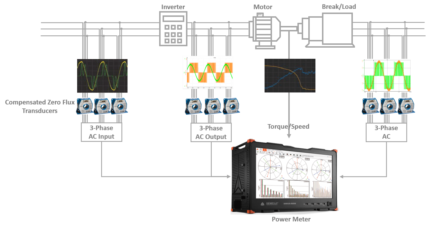
In this Pro Training the correct way to measure the electrical power of different systems will be explained as well as for different applications such as grid, motor and inverters among others. First of all, the theoretical part will be covered, including a theoretical background on power calculations. Secondly, the calculation of easy power parameters and explanations of how to configure the power module and how to visualize the power parameters in the measurement screen of the Dewesoft software. Lastly, there is a practical part showing step-by-step how to measure DC power, single phase, 2-phase, 3-phase in star, delta, Aron and V-connection AC power, as well as what is to consider when measuring inverters and an example of how to calculate the power of a 6-phase motor.Image 2: Schematic illustration of a complex 3-phase measurement

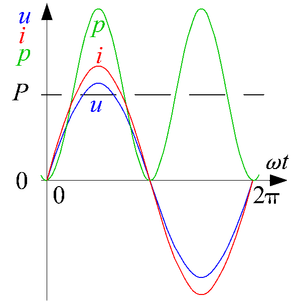
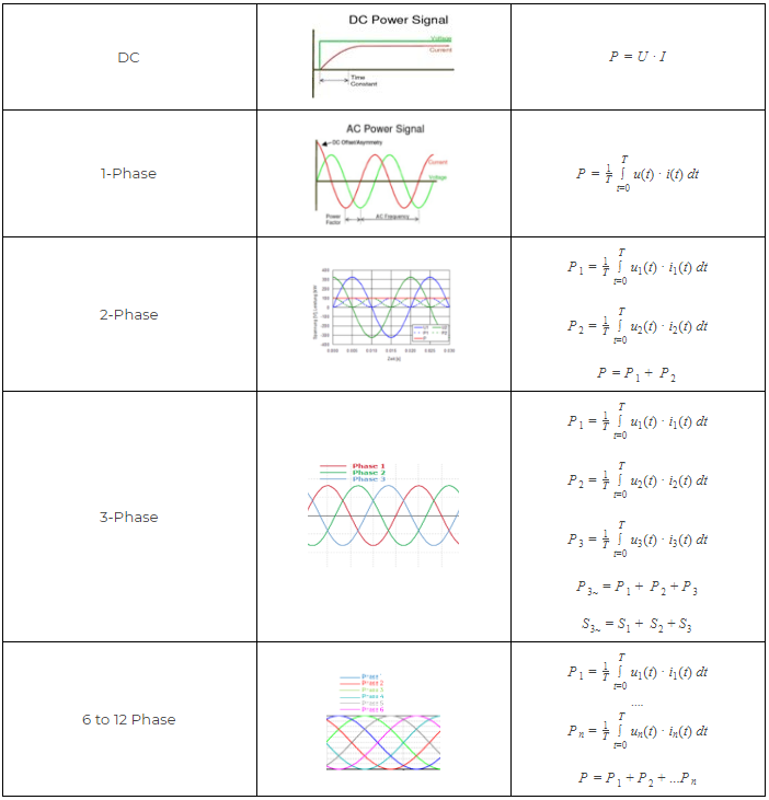
Electrical power is the rate at which electric energy is transferred by an electric circuit. The SI unit of power is watt [W]. The following formula describes the calculation of the electric power for AC or DC systems in general.

\[P = \frac{1}{T} \int_{t=0}^T u(t) \cdot i(t)dt \]

Image 3: Power calculation graph

                                                                                P is power in Watt [W]            u is voltage in Volt [V]

                                                                                i is current in Ampere [A]        T is the periodic time in seconds [s] 

So, the power is not just voltage multiplied with current as was initially stated, it's the integration over the periodic time of this term, divided through the periodic time. This means that it is a requirement to know the period of time (frequency) to calculate the power of an electrical system.

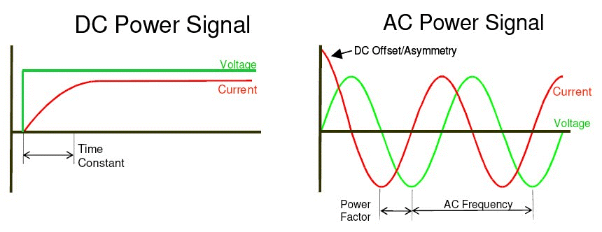
Measuring DC power is not as complicated, as the voltage and current are constant and there is no frequency as seen in the image below. The time interval for the integration just defines the average interval of the power calculation.

Image 4:Direct current and alternating current wave-forms

To measure AC systems the periodic time needs to be known. This cannot be done by taking the normal grid frequency (e.g. 50 Hz) as a constant. This is due to the fact that the grid frequency is ever changing depending on the balance of the energy supply and the electric load at that exact moment. With variable drives, where the frequency continuously changes with a large bandwidth (ranging from 1 Hz up to 2000 Hz) makes it even more difficult to calculate the power. Therefore, the period time must be determined. This is especially difficult when measuring inverters where the voltage is not a sinusoidal waveform anymore but packets of pulses.

Frequency Determination

This is where the Dewesoft power analysis tool distinguishes itself from the conventional power analyzers. Conventional power analyzers use a zero-point detection to determine the periodic time. This means that they evaluate when the voltage or current crosses that x-axis and use that value to calculate the periodic time. This works well most of the time, but especially when measuring strongly distorted signals this method can lead to measurement errors.


Dewesoft was not happy with "works well most of the time". Therefore, a special FFT (Fast Fourier Transform) algorithm (Software PPL) to determine the periodic time (frequency) was developed. The algorithm determines the periodic time of the signal via a special FFT algorithm using a sampling window of multiple periods (typically 10 periods, definable in the power module). The calculated frequency is highly accurate (mHz) and works for every application (motor, inverter, grid, ...).

How a low-cost Watt-meter calculates the power of an AC system

A low-cost watt-meter calculates the power of an AC system out of the peak values from the voltage and the current, according to this formula:

\[U_{RMS}=\frac {u_{peak}}{\sqrt 2}\]

In order to calculate the power, they simply multiply the RMS values of the voltage and current. This way of measuring the power works well when the waveform for both current and voltage is an ideal sinusoid (as it is produced in the generators at power-plants). Nowadays the waveform of both voltage and current are never ideal due to non-linear loads and also non-linear generation units. This way of calculating the power is outdated, especially when measuring inverters, the calculation will mostly be completely wrong.

How a Conventional Power Analyzer Calculates the Power of an AC System?

Conventional power analyzers calculate the RMS values of the voltage and current out of each sample point. The RMS values are calculated out of the square root of all squared sample points of the curve divided by the number of samples.

\[RMS = \sqrt{ \frac {1}{n} \sum_{i=1}^n U_i^2 } \]

How Dewesoft Power Analyzer Calculates the Power of an AC System?

As mentioned earlier conventional power analyzers calculate the power in the time domain. Dewesoft on the other hand calculates power in the frequency domain. With the predetermined period time, an FFT analysis for voltage and current is done for a definable number of periods (typically 10, with electrical applications) and a definable sampling rate. 

The FFT yields an amplitude for the voltage, current and the cos phi for each harmonic. One major benefit of this FFT transformation is that the behavior of amplifiers, current or voltage transducers in amplitude and phase for the whole frequency range (using the Sensor XML) can now be corrected. This way of power analysis has the highest possible accuracy. Another benefit is that harmonic analysis and other power quality analysis can be done completely synchronized to the fundamental frequency.

With the FFT corrected values, the RMS voltages and currents are calculated out of the RMS values of each harmonic.

\[U_{RMS_{total}} = \sqrt{U_0^2 + U_1^2 +U_2^2 + \cdot \cdot \cdot + U_n^2  }\]

\[I_{RMS_{total}} = \sqrt{I_0^2 + I_1^2 +I_2^2 + \cdot \cdot \cdot + I_n^2  }\]

The power values for each harmonic and the total values are calculated wit the following formulae: 

 Table 1: Alternating current  power equations

Some of the benefits of the Dewesoft power calculation method compared to conventional methods are as follows

  • Raw data storing simultaneous to power analysis
  • Additional sensor calibration for amplifier and sensors for amplitude and phase for the full frequency spectrum
  • Easy power quality analysis (harmonics, inter harmonics, higher frequencies)
  • Resampling
  • Period values for power, voltage, current and symmetrical components 

AC power can be classified into three different types of power, these are called active power, reactive power and apparent power. 

Power triangle

The power triangle illustrates the relation between active, reactive and apparent power.

Image 5: Power triangle

In the diagram, P is the active power, Q is the reactive power (in this case positive), S is the complex power and the length of S is the apparent power. Reactive power does not do any work, so it is represented as the imaginary axis of the vector diagram. Active power does do work, so it is the real axis.


Active power - P

Active power is measured in Watt (W) and refers to the energy transfer from an electric generator to a load. The active power is the power which can be used by electric loads (useful power).

\[P =  U \cdot I \cdot cos(\varphi)\]

Reactive power - Q

The reactive power is measured in Volt-Ampere-reactive (VAr). The reactive power doesn't consist of energy but is necessary for most types of magnetic equipment (motors, transformers) to work. Reactive power is provided by generators, synchronous condensers or electrostatic equipment such as capacitors and directly influences the electric system voltage and also the capacity of the power transmission line.

\[Q = U \cdot I \cdot sin(\varphi) = \sqrt{S^2 - P^2}\]

Apparent power - S

Apparent power is measured in Volt-Amperes (VA) and is the voltage on an AC system multiplied by the total current that flows in it. It is the vector sum of the active and the reactive power.

\[S = U \cdot I\]

Power factor

The ratio between active power and apparent power in a circuit is called the power factor. For two systems transmitting the same amount of active power, the system with the lower power factor will have higher circulating currents due to energy that returns to the source from the energy storage in the load. These higher currents produce higher losses and reduce the overall transmission efficiency. A lower power factor circuit will have a higher apparent power and higher losses for the same amount of active power. The equation is multiplied by 100 to yield the power factor in percent.

\[ PF = \frac{P}{S} \cdot 100\]

Cos Phi

Cos phi is the angle difference between a phase voltage relative to the current. The difference between cos phi and the power factor is that the cos phi is calculated for each individual harmonic starting at the fundamental frequency compared to the power factor which includes the whole spectrum (all harmonics).

Power triangle analogy to beer 

It is easier to understand the power triangle using a beer analogy. The reactive power is like the foam (head) on top of the beer. The active power is the actual liquid gold in the glass. The foam in the glass does take up space and thereby reduces the volume that the actual beer has in the glass. The foam is a natural part of the process of pouring beer, but one does try to keep it as low as possible to increase the volume in the glass for the Beer. By comparison the reactive power will always be in the transmission lines and reduce the capacity in which real power can be transported, but it is kept as low as possible. Only the active power can be used.

Image 6: Power triangle analogy to beer

 Calculation of power values (P, Q, S) for each harmonic

To easier understand how the power of each harmonic component is calculated, refer to the image below illustrating the calculation of several harmonic active power values. The same calculation is done for both apparent and reactive power, just using different equations.

Image 7: Calculation of harmonic active power values

The new power triangle

Nowadays the typical power triangle that was illustrated above doesn't comply with the times anymore because other parameters such as distortion or harmonic reactive power have to be considered in the new power triangle as illustrated below. This new triangle shape is mainly due to more and more non-linear loads (inverter, electronic ballast unit, etc...) and also new power generation units (the wind, PV, etc...). The new power triangle, therefore, has an additional dimension added to it:Image 8: New power triangle

Harmonic reactive power - QH

The sum of the harmonic reactive power. This reactive power occurs through the phase shift between voltages and currents of the same frequency.

\[QH = \sum_{h=1}^H Q_h\]

Distortion reactive power - DH

The combination of voltages and currents of different frequencies which produce the distortion power.

\[DH = \sqrt {Q^2 - QH^2}\]

Name in Dewesoft X (e.g. for L1): DH_L1, distortion power of all harmonic components' reactive powers where u and i have different harmonic orders.

Distortion - D

Distortion power considers everything except the first harmonic.

\[D = \sqrt  {Q^2 - Q_{h=1}^2}\] 

Name in Dewesoft X (e.g. for L1): D_L1, distortion power of all harmonic components' reactive powers (u and i have the same order but not equal 1 or have a different order)

These are the power quality (PQ) parameters. All other PQ parameters which are calculated in Dewesoft X (Harmonics, THD, Rapid voltage changes, Symmetrical components ...) can be found in the chapter, Power Quality.

Calculation of power values (P, Q, S) for each harmonic for the new power triangle

Image 9: Calculation of harmonic power values for the new power triangle


Energy calculation

The Dewesoft X software can automatically calculate the measured system's energy using the power module. It's possible to calculate the total energy consumption or it can be split up into positive (energy consumption) and negative energy (energy delivery). This is helpful when measuring electric vehicles with recuperation (energy recovery) or when measuring the load profile of households/industry which have a power generation unit e.g. photovoltaic.

The energy calculation is a simple integration of all power values. To get the positive energy, the positive power values are integrated, for the negative energy the negative power values are integrated. A selection can be made between positive, negative or both.

Table 2: Energy calculation formulae in the power module

 P is power in Watt [W] and E in energy in Watt hours [Wh].

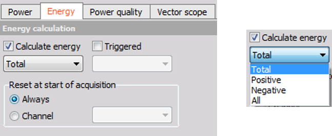
In the following images the settings for the Energy calculation in the power module are shown.


Image 10: Energy calculations in the power module 

In addition to the basic power calculations it is also possible to start/reset the energy calculation at trigger events. Otherwise, the energy will be calculated as soon as you switch into measure mode. It is also possible to reset values at start of acquisition or with a channel.

Efficiency calculation

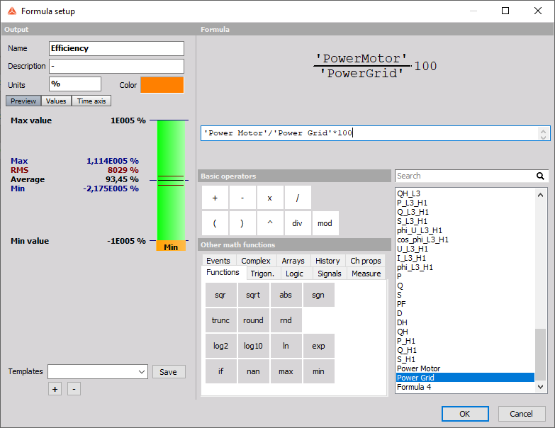
The efficiency of electrical devices can easily be calculated using the Dewesoft Math library, using the Formula editor. It can be calculated for power or for energy values, during the measurement as well. 

\[\eta =  \frac {P_{motor}}{P_{grid}} \cdot 100 \]

Where η is the efficiency in [%]

Image 11: Efficiency calculation in the power module 

There are applications where the energy is measured at multiple points for instance in electric vehicles that use recuperation of energy. The following Sankey diagram is a representation of the energy flow that would likely be measured with a recuperation electric vehicle.

Image 12: Sankey diagram of an electric vehicle


The power module is one of the most complex mathematical modules in Dewesoft X. It allows measurements of different frequency power grids in different configurations and even variable frequency sources. This section will demonstrate how to use it.

After the configuration of the voltage (please refer to the voltage pro training) and current (please refer to the current pro training) inputs it is now possible to add a new power module by clicking on the "+" button in the channel set-up. Then click on the "power analysis" button by doing this the power icon will be available. Image 13: Activating the power module in Dewesoft X The following image gives an overview of the power module set up screen.

Image 14: Overview of the power module setup screen

 Power module configuration and wiring

In the power module, there are several wiring schematic configurations available. The most common ones are 1-phase and 3-phase star and 3-phase delta connections. 2-phase is used with special motors and also in some applications of the grid. The Aron and V configuration are basically star or delta configuration but measuring only 2 currents instead of 3 (see 3-phase measurement). Special configurations like 6-, 7-, 9- or 12 phase motor measurement can be done with multiple single-phase systems and adding up the power values in the Math library.

The wiring schematics are covered in a later chapter, while this chapter focuses on the configuration of the power module,

Image 15: Wiring schematics in Dewesoft X  

 Line Frequency

Firstly, the line frequency must be set. In the public grids the frequencies are 50 Hz for Europe and 60 Hz in the USA (please make sure that the correct frequency is set for the region where the measurement will take place). There are also other line frequencies available (16,7 Hz, 25 Hz, 400 Hz, 800 Hz) for special applications. For inverter measurements "variable frequency" must be selected. The "variable frequency" setting searches automatically for the fundamental frequency in the signal via an FFT algorithm (highest peak).

Table 3: Line frequencies in Dewesoft X 

 This algorithm calculates the frequency with very high accuracy (mHz) but is also very CPU intensive (CPU power). For optimal performance, it's recommended to set a range (start and end frequency) where the fundamental frequency could be via the "Exact frequency settings". For example, when measuring an inverter driven motor and it is known the fundamental frequency is no higher than 200 Hz it is recommended to add an end frequency a little higher than the known frequency for example at 250 Hz.

Image 16: Start and end frequency ranges  

Output limits

When measuring high power, it could be useful to change the output unit to a higher unit. Available are Watt, Kilowatt and Megawatt.

Image 17: Output units in the power module 

Frequency source

A special functionality in the power module is the selection of the frequency source. As a source, the voltage, the current, external signal or an arbitrary channel can be selected.

Image 18: Frequency source in the power module 

Arbitrary channel uses filters for better and more stable frequency determination. For all different types of frequency sources, it is possible to select the channel which should be used for the frequency calculation.

If there are more than one power module, it is possible to synchronize the modules with arbitrary channels. (E.g. by selecting one phase out of another power module)

As seen in the following image of an inverter measurement, the voltage (green) is not a sinusoidal waveform any more. It has become a packet of pulses. In this case, if voltage is selected as the frequency source there is a chance that the determination might be faulty. On the other hand, the current waveform (orange) has a nice stable sinusoidal form and should rather be selected as the frequency source as this will yield much better results. The oscilloscope function in the Dewesoft X software is extremely helpful in analyzing the signals for frequency source determination.

Image 19: Voltage PWM signal and a sinusoidal current signal 

 Number of cycles

In this option, the number of cycles for the power calculation can be set as shown in the image below on the left-hand side. As standard, this value is 10 periods for 50 Hz measurements and 12 periods for 60 Hz applications (required in the 61000-4-30 standard). In the dropdown list only 10 and 12 cycles are selectable, but any arbitrary number up to 999 can be entered into the field, the lowest number of periods is 5. For all other applications, if there is a need for faster values the "period values" functionality can be used, please ensure that this function is enabled by clicking in the checkbox, it is activated when there is a tick in the box as seen in the image on the right-hand side.

Image 20: Number of cycles and period values in the power module

 Nominal voltage

The entry of the nominal voltage is important if you want to calculate the Flicker values. For other measurements the voltage should be set to at least an approximate voltage of the measurement. If this value is set very high (e.g. measuring inverter with 20 V output and the nominal voltage is selected to 400V) the frequency determination might fail.

Example:

  • 230 V - line to earth voltage for star configuration
  • 400 V - line to line voltage for delta configuration
Image 21: Nominal voltage selection in the power module

In the drop-down list 120 V and 230 V is available, but it is possible to enter any arbitrary voltage that is required for the measurement in the nominal voltage field.

Calculation sample rate

The calculation sampling rate in the power module is like a sample rate divider for the power calculations. At high sampling rates (>100 kHz) this is often necessary due to performance problems (CPU power reaching its limit). Nevertheless, the calculation rate that is required shall be selected for the measurement. If all the data is stored at the full sampling rate (always fast) it is also possible to calculate in the power module at the full calculation rate in the post-processing function.

Typical calculation rates:

  • grid measurement - 10 to 20 kHz
  • wind, renewable, etc. - 50 kHz
  • inverter measurement - 100 kHz or more


Image 22: Calculation sample rate in the power module 

After all the configurations have been done, the channel list will show which parameters will be calculated by the Dewesoft X software.

Table 4: Channel names for power period value calculations in the power module
Table 5: Channel names for total power calculations in the power module

The power module calculates many parameters. Most of the time not all these parameters are needed for the current application. In this case it is possible to deselect some of the unneeded parameters. This will reduce the data file sizes (The size of the reduction relies strongly on the number of deselected parameters but also on the parameter calculation intensity as these also differ).

Image 23: Channel list in Dewesoft X 

Multiple power modules

In the Dewesoft X software multiple power modules can be created. This means that power can be measured at multiple points completely synchronous. In the math library the power modules can be further refined, for example the efficiency can be calculated automatically (see efficiency calculation). This is also very helpful when measuring multi-phase motors (6-12 phases). Just click on the + next to the already active power modules to add another one.

Image 24: Multiple power modules


 Period values

Period values are needed to perform a detailed analysis of electrical equipment (e.g. analyzing behavior at faults or switching processes) and for fault recording (as a trigger argument). The period values are calculated for voltages, currents, active-, reactive-, apparent-power, power factor as well as other parameters.

The period values can be calculated with a definable overlap (up to 99%) and for a definable number of periods (up to 4). Using an overlap of 99% at a 50 Hz measurement you can calculate the power values for every 0,2 ms. That's a unique feature of Dewesoft X.

Overlap: 25%, 50%, 75%, 90%, 95%, 99%

Periods: 1/2, 1, 2, 4


Image 25: Period values in the power module 

The period values are not corrected in amplitude and phase as is the case for the other power calculations in the power module.

Considering the period values for the symmetrical components (for more details please see the Power Quality Pro training) there are more than 50 parameters available.


Table 6: Period value calculations for each phase in the power module 
Table 7: Total Period value calculations in the power module


Image 26: Power calculations for different wiring schematics 


The following section will go into more detail on the possible measurement setups that are available in Dewesoft X. We will show how to connect both voltage and current in various setups, along with explanations on setting up the measurements in the software. There are also a few screens that show what the possible measurements could look like when the setups are done and measurements are made.

DC power measurement

Hardware configuration

For a simple DC measurement please connect the voltage and the current to the Sirius as it is shown in the following image.

Image 27: DC measurement hardware configuration

 Analog setup

In the next step the analog setup must be done in Dewesoft X for both the voltage and the current (Please refer to the pro training's on current on voltage as references). The image below shows what a typical DC set-up would look like.

Image 28: DC measurement analog setup

 Power module setup

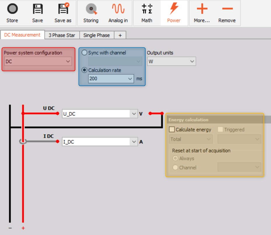
In the power module, the wiring must be set to DC measurement, this is illustrated in the image below in the red square. Then configuration for the selected application must be done. 

On the wiring schematic page, it is possible to select two different calculation modes, this is illustrated in the blue square in the image. Firstly, it is possible to select or type the required calculation rate, or the measurement can be synchronized to another channel. This synchronized channel can be from another power module e.g. a 3-phase power module. Additionally, an energy calculation can be added, as seen in the yellow square in the image. 

Image 29: DC measurement power module setup  

DC Math power calculation (only required in Dewesoft X2)

In Dewesoft X2, a simple math formula needs to be created, by multiplying the DC voltage with the DC current the DC power is calculated.

Image 30: DC math power calculation (only required in Dewesoft X2)


Measurement screen

Switching to the measurement screen the voltage, current and power can be visualized. In the image below, the battery power of an electric vehicle is shown. The voltage (magenta) is relatively constant while the current (green) is only present when power (acceleration - blue) is actuated.

Image 31: DC measurement recorder screen

1-Phase Measurement

Hardware configuration

For a single-phase AC measurement please connect the voltage and the current to the Sirius as it is shown in the following picture.

Image 32: 1-Phase measurement hardware configuration

Analog setup

In the next step the analog setup must be done in Dewesoft X for both the voltage and the current (Please refer to the pro training on current on voltage as references). The image below shows what a typical 1-Phase set-up would look like.

Image 33: Single phase measurement analog setup  

Power module setup

In the power module, the wiring must be set to single phase and the configurations for the specific application must be done.

For example, measuring a load connected to the public grid the line frequency will be set to 50 Hz (60 Hz in North America, parts of South America, Japan, etc.), the output unit should be Watt, the frequency source is voltage, number of cycles are 10 (12 in case of 60 Hz) and the nominal voltage (line to earth) is 230 Volts in Europe ( this varies from country to county). In the drop down list 120 V and 230 V can be selected, but in the input mask it is possible to enter the value that corresponds to the measurement.

Image 34: Single phase power module setup screen 


Measurement screen


After switching to measurement mode, the screen design for the measurement can be set up to the requirements of the user. The image depicts a measurement screen with most common graphs and values that are measured in a 1-phase measurement.  

Image 35: Single phase measurement screen

2-Phase measurement

2-phase measurements are seldom, but some motors (e.g. step motors) for example are operated with two phases (one phase has a phase shift of 90° to the other).

Hardware setup

For a 2-phase AC measurement please connect the voltage and the current to the Sirius as it is shown in the following image.

Image 36: 2-Phase measurement hardware setup

Analog Setup

The next step would be setting the analog setup for the voltage and current input (please refer to the pro training on voltage and current for more information).


Image 37: 2-Phase measurement analog setup

Power module setup

In the power module, the wiring must be set to 2-phase and the configurations for the specific application must be done.

Image 38: 2-Phase measurement power module setup screen

Measurement screen

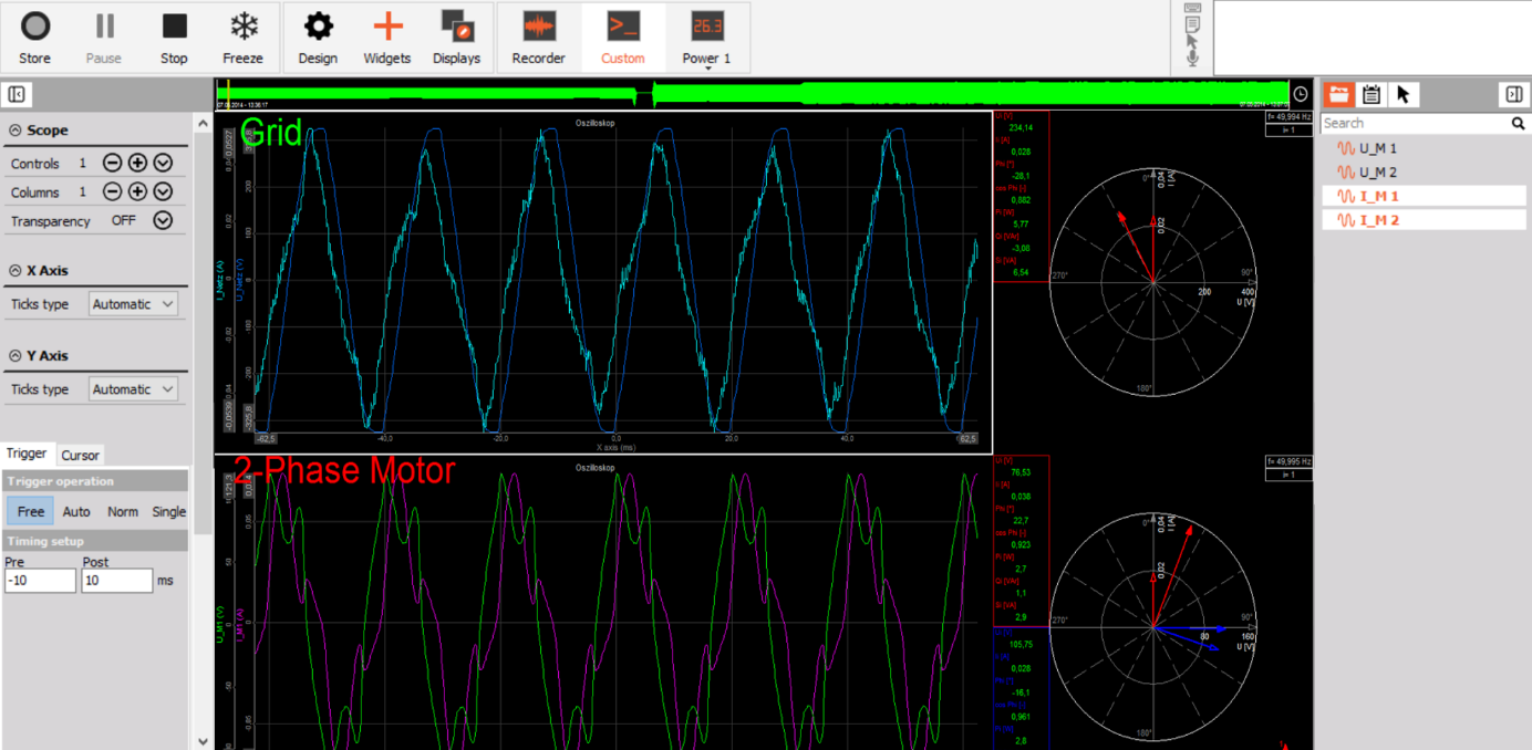
After switching to measurement mode, the screen design for the measurement can be set up to the requirements of the user. In this case, the scope and vector scope of a 2-phase step motor is shown as well as the single-phase voltage and current of the grid.

Image 39: 2-Phase measurement screen

3-Phase star measurement

The star connection is mainly used for measuring 3-phase systems, especially if a neutral line from the grid or the star point of a motor is available. The three phase voltages are connected to the Sirius HV modules on the high voltage side. The low voltage side of the three inputs is on the potential of the neutral line or motor start point. If both are not available an artificial star-point can be created by short-circuiting the low sides of the amplifiers.

Hardware configuration

The following image shows the connection for a 3-phase star measurement including three zero flux transducers for current measurement. In this measurement zero flux transducers are used therefore, a Sirius MCTS slice needs to be connected as well. This is because the zero flux transducers need more power than the Sirius 4xHv 4xLV can deliver. The Sirius MCTS is designed to deliver power up to 20W per channel.  

Image 40: 3-Phase star measurement hardware setup 

Analog setup

The next step would be setting the analog setup for the voltage and current input (please refer to the pro training on voltage and current for more information).

Image 41: 3-Phase star measurement analog setup 

 Power module setup

In the power module, the wiring must be set to 3-phase star and the configuration for the specific application must be done.

Image 42: 3-Phase star power module setup

 Measurement screen

After switching to measurement mode, the screen design for the measurement can be set up to the requirements of the user. In this example the load of a household is shown.

On the top left of the screen there are digital meters that display the voltage and current values in RMS, in the middle is the current power that is being consumed from the grid and on the top right-hand side current power values of the three phases are shown. The left scope in the middle of the screen shows the waveform of the voltage, and the right one the waveform of the current (which is quite distorted). At the bottom of the screen the load profile is shown in a recorder.

Image 43: 3-Phase star measurement screen

3-Phase delta measurement

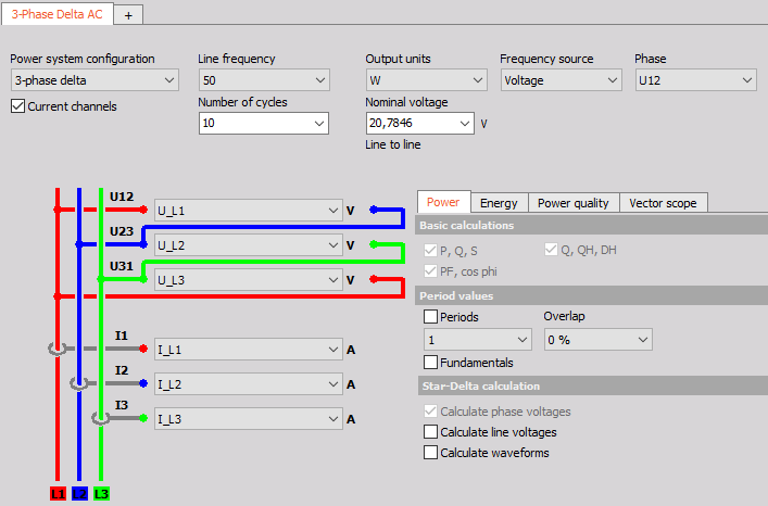
The delta connection is used in the absence of a neutral line or star point on a motor. The three phase voltages are connected to the Sirius HV modules on the high voltage side to the live terminals (Red). The neutral terminals of the HV amplifier must be connected to the next live terminal (neutral terminal L1 to live terminal L2, neutral terminal L2 to live terminal L3 and then the neutral terminal L3 to the live terminal L1).

Hardware configuration 

The following image shows the connection for a 3-phase Delta measurement including three zero flux transducers for current measurement. In this measurement zero flux transducers are used therefore, a Sirius MCTS slice needs to be connected as well. This is because the zero flux transducers need more power than the Sirius 4xHV 4xLV can deliver. The Sirius MCTS is designed to deliver power up to 20W per channel.

Image 44: 3-Phase delta measurement hardware setup

 Analog setup

The next step would be setting the analog setup for the voltage and current input (please refer to the pro training on voltage and current for more information).

Image 45: 3-Phase delta measurement analog setup

 Power module setup

 In the power module, the wiring must be set to 3 phase-delta and the configuration for the specific application must be done.


Image 46: 3-Phase delta power module setup


 Measurement screen

After switching to measurement mode, the screen design for the measurement can be set-up to the requirements of the user. In this example the measurement of a PV inverter in delta configuration is shown. The vectorscope on the top right shows that the power is being fed into the grid, therefore the current vectors have a phase shift of 180° to the voltage vectors compared to where they would be if the system was consuming power. Further illustrated are the waveforms of both voltage and current on the scopes as perfect sinusoidal waveforms. 

Image 47: 3-Phase delta measurement screen

As a comparison in the next image a 1-phase PV inverter is depicted, with unfavorable wave-forms for both voltage and current. The voltage has a rectangular waveform, electrical devices like this one puts large amounts of stress on the grid. This is mainly due to harmonics that are present in the signals, they cause distortion in voltage and current waveforms causing them to take on different waveforms compared to the ideal Please refer to the Power Quality pro training for more information.

Image 48: 1-Phase PV inverter measurement screen

Star - Delta calculation

A special feature in the Dewesoft X power module is the star-delta calculation.

Image 49: Star-Delta calculation

This feature allows for the calculation of all values of a delta connection out of a star connection (waveform, RMS values) and vice versa. This means that no matter the hardware connection to the system, both connection types can be measured. For example, to see the analog voltage signal of a delta connection when a star connection is being used, just select the option "Calculate waveforms" highlighted in BLUE in the figure. The next option highlighted in RED "Calculate line voltages" allows RMS voltages and harmonics to be displayed.


Image 50: Calculate line voltages and calculate waveforms

  The following table shows the calculations that are used in Dewesoft X to do the star-delta and the delta-star conversions.


Image 51: Star-Delta and Delta-Star conversion calculations in the power modules


Aron, V-connection and 3-phase 2-meters


With some applications, only two currents and / or voltages are measured instead of three in a three-phase arrangement. The main reason for this type of measurement is to save costs.

This is done for measurements where it is completely sure that the load is absolutely synchronous, the third current can then be calculated from the two currents that were measured. This is often done with grid measurements (expensive current transducers, symmetrical load).

Aron connection

Hardware configuration

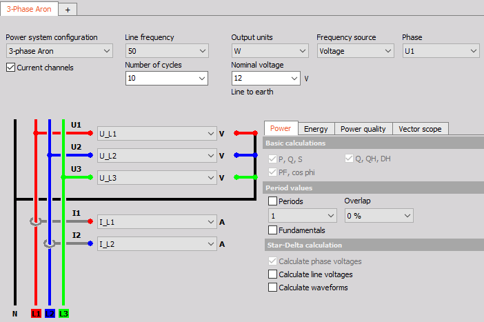
The most common way of measuring active power with symmetrical and asymmetrical loads without an N connection is the two-power meter circuit or Aron circuit. It has the advantage over the three-power meter circuit that it saves one measuring device and that cos phi and reactive power determination is also possible with a symmetrical load. The Aron connection is a star connection where only two currents are measured.

Image 52: Aron connection hardware setup

 Power module setup

In the power module, the wiring must be set to 3-phase Aron and the configurations for the specific application must be done.

Image 53: Aron connection power module setup

V-connection

Hardware configuration

The V-connection is a delta connection where only two currents are measured, but fundamentally works with the same principle as the Aron connection.

Image 54: V-connection hardware setup

 Power Module setup

In the power module, the wiring must be set to 3-phase V and the configurations for the specific application must be done.

Image 55: V-connection power module setup 

3-Phase 2-meters connection

Hardware configuration 

The 3-phase 2-meters Connection is a delta connection where just two voltages and two currents are measured.

Image 56: 3-Phase 2-meters hardware setup

 Power module setup

In the power module, the wiring must be set to 3-phase 2-meters and the configurations for the specific application must be done.

Image 57: 3-Phase 2-meters power module setup 


Inverter measurement

When measuring inverters or after the inverters care must be taken as there are a few things that have to be considered to ensure that the correct results are yielded with the highest possible accuracy.

High-speed amplifiers

Always use high-speed (HS-HV and HS-LV) amplifiers for measuring inverters. As the voltage is modulated (amplitude or phase) with switching frequencies up to several hundred kilohertz, therefore, it is absolutely necessary to use high-speed amplifiers to get correct results.

Image 58: SIRIUSi 4xHV 4xLV DAQ

Current sensors

There are a lot of higher frequency components and some DC components contained in measurements of inverters or after inverters. Therefore, please ensure to always use current sensors with high bandwidth capabilities as well as having the capability to measure both DC and AC currents. The recommended current transducers to use would be Dewesoft zero-flux transducers, flux-gate current clamps or hall-compensated AC current clamps (Please take note that Fluxgate and Zero-flux current sensors require a PWR-MCTS to power them).

Image 59: Current sensors for inverter measurements

 Frequency source


It is important to set the current as frequency source for this measurement, because the voltage out of an inverter hasn't got a sinusoidal waveform any more. The inverter has modulated the signal by pulse width or amplitude, so it's a packet of pulses. In the following image an inverter modulated voltage (green) is depicted. The current (orange) has a sinusoidal waveform and should therefore, be used as the frequency source.

Image 60: Frequency source for inverter measurements

 Measurement configuration

The choice of either using a star or a delta connection for measuring after inverters is open and can be freely selected by the user. Please note that an Aron or a V-connection should never be used for this type of measurement. For basic power analysis, a delta connection is a commendable choice, especially if there is no star-point available. But please use caution as the measurement is made between voltages this connection is not always suitable for a detailed inverter analysis (analysis of switching pulses).

When measuring with a star point connection a star point adapter should always be used. The artificial star point via the modules doesn't conform due to differences in impedances. The active power analysis will not be affected by this, but the analog signals that are displayed will be false. The apparent power and the power factor that this type of measurement will yield will also be false. Using a star connection with a star point adapter will yield very accurate power values as well as the true analog signal which can then be used for a detailed power analysis.

The best way of measuring an inverter is using the star connection with a star point adapter. If this is not possible then opt for the delta configuration.

Motor cable shielded or unshielded

A frequently asked question when measuring an inverter: Is there a difference when measuring with or without a shielded motor cable?

The answer is, yes, there could be a difference. Due to the high switching frequencies of the inverter there could be leakage currents via the shield of the cable. This leakage current can affect the results in the following ways:

  • Phase shift - it's possible that a phase shift occurs. Comparative measurements, where a motor cable was measured parallel with and without shielded motor cables, has shown that the phase shift can be more than 15°.

  • Bandwidth damped - with shielded motor cables it is very likely that the signal is damped, especially at higher frequency parts.

  • Higher DC current - with the measurement of the shielded motor cables there is a possibility of a higher DC current occurring.

Therefore, this capacitive leakage can have low-pass characteristics (phase shift, no higher frequencies) and can affect the measurement results.

Measurement screen

After configuring the power module, the measurement screen(s) can be configured in measurement mode. As discussed earlier different visualization modes can be added by switching to design mode. The visualizations that are available are located at the top of the window. On the right side of the window is the channel list and on the left side is the properties of the different visualizations.

Image 61: Visualization overview of the measurement screen in the power module 


The most relevant visualizations for power analysis are:

  • Digital meters (depicts the different instantaneous values calculated out of the power module)
  • Recorder (depicts the chart of power values)
  • Scope (depicts waveforms of voltages and currents)
  • Vector-scope (depicts the relation between the voltages and currents)
  • Harmonic FFT (depicts the harmonics of voltage, current, power and reactive power synchronized to the fundamental frequency of the signal) 
Image 62: Most relevant visualizations for power analysis 


Channel list

In the channel list you now find all the parameters which are automatically calculated out of the power module. They are categorized to easily find the desired values:Image 63: Channel list in the power module

In the next section the vectorscope and the harmonic FFT will be described in more detail as these two visualizations were specifically implemented for power module calculation.

 Vectorscope

"Vector scope" means that not only the absolute values of current and voltage are important but also the phase relation between current and voltage. This is essential as only current that is in phase with the voltage can be used to produce useful work.

Therefore, in the vector scope both the absolute values and the angle known as the angle phi is measured. From the angle phi the value of cos phi can also be calculated (which in principle is just the cosine of the angle phi, this is important because it is the direct ratio of work that is done compared to the consumed current). In the vector scope the voltage vector (hollow point arrow) and the current vector (full point arrow) for each harmonic can be shown.

Image 64: Vectorscope settings

Dewesoft X has a special feature where the vectorscope's orientation can be changed. This means that the scope can be shown in a clockwise and in an anti-clockwise manner, and it is also possible in some special applications to change the vectorscopes' orientation to the right. This can be changed in "Settings'' ->  "Extension" -> "Power grid analysis". The default setting is to show the vectorscope for the first harmonic. Via the input field "shown harmonic" in the visualization properties each individual harmonic can be selected.

Image 65: Changing the orientation of the vectorscope in Dewesoft X

Furthermore, the scaling for voltage and current can be defined either manually or automatically. The option "Show measured values" adds digital values of basic power parameters for each phase on the right and left side of the vector scope. The option "Tick count" defines the number of circles to be shown.

  • upper, CW - zero is top, the positive phase angle is right
  • right, CW - zero is right, the positive phase angle is right
  • upper, CCW - zero is top, the positive phase angle is left
  • right, CCW - zero is right, the positive phase angle is left

Harmonic FFT

In the power module the harmonics can be calculated for apparent-, active- and reactive-power for each individual harmonic. But is it necessary to calculate the harmonics?

In theory, voltage and current have a perfect 50 (or 60) Hz sine wave. This is the case if there are just linear loads (Ohmic) connected to the grid (e.g. incandescent light bulbs). But as there are more and more non-linear loads connected (ballast unit, inverter, etc.), some generation units are not linear anymore either e.g. Wind, PV, etc., therefore the waveform of voltage is not an ideal sinusoidal wave anymore. The images below show the voltage and current of an incandescent light bulb (left) and a LED (right). It can clearly be seen that the incandescent light bulb waveform for current (blue) is sinusoidal but the current of the LED (red) is a pulse waveform with a high crest factor.

 Image 66: Scope view of a pure ohmic load and a non-linear load

 The following Harmonic FFTs depicts the big difference of the two different loads (current harmonics):

Image 67: Harmonic FFT view of a pure ohmic load and a non-linear load 

What is the effect of harmonics? Using an AC electromotor, the first harmonic (line frequency) drives the motor. The rest of the harmonics are either producing vibrations or noise. In truth there are bad and then there are worse harmonics. The 2nd, 5th, 8th... harmonics are really bad since they are braking the motor. The 3rd, 6th, 9th... harmonics are either driving or braking, while 4th, 7th, 10th... harmonics are driving the motor, but they are still producing high noise and vibrations.

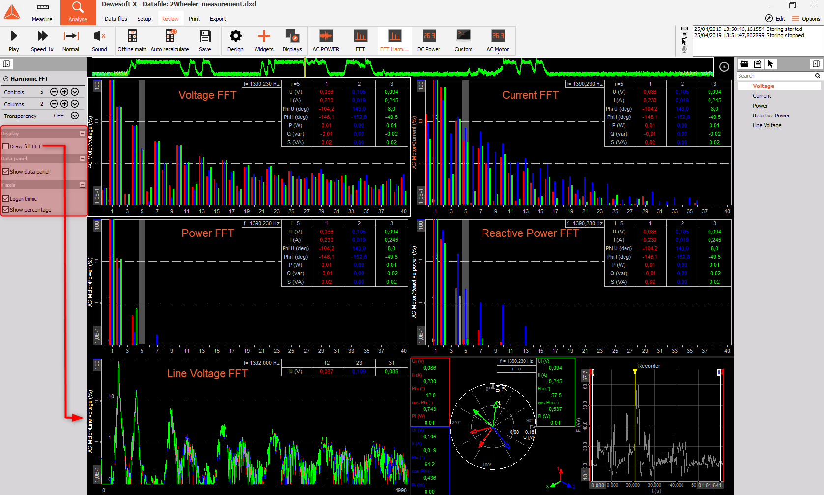
In the Harmonic FFT the following can be visualized, harmonic - voltage, current, active and reactive power as well as the line voltage each fully synchronized to the fundamental frequency.

Image 68: Harmonic FFT options in Dewesoft X

 In the visualization properties, there are additional options available:


  • Show Data Panel - The power values of each harmonic can be displayed in the top right corner of the FFT when "Show Data Panel" is selected. The individual harmonic values can be shown by clicking on the order number.
  • Y-Axis - Here the harmonics can be displayed on a linear or logarithmic scale, as well as if they are shown in an absolute or percentile relative to the fundamental frequency.
  • Draw full FFT - The option "Draw full FFT" shows all frequencies, not only multiples of the fundamental frequency. As seen in the Line Voltage FFT in the Image.

More details about harmonics and full FFT will be given in the Power Quality Pro Training.

All the most common configuration setups are available in the DewesoftX power module. But especially in E-Mobility there are applications and configurations for 6-, 7-, 9- or even 12 -phase motors needed. There can be various reasons for this such as lowering the voltage level or reducing the stress on the components.

With conventional power analyzers there is no way to do a comprehensive analysis of such motors. But with the modular hardware systems of Dewesoft in combination with its powerful software these types of applications do not present any type of challenge.

For example, a 6-phase motor can be measured by using 6 single-phase power modules and calculating the total power in the power module.

Image 69: 6-Phase motor measurement setup

This application should demonstrate how powerful the Dewesoft Power analyzer is.


Should the situation arise where the computer that is being used for the measurements has inefficient computing power to calculate all the parameters that are available, there are a few tips that could help with that.

  • Acquisition rate - the acquisition rate should be set to suit the respective application. Often lowering the acquisition rate doesn't affect the measurement results. With inverter measurements, the sampling rate should be 10 - 20 times that of the switching frequency.

  • Calculation rate in the power module - lowering the calculation rate often doesn't influence the power calculation. The benefit of this compared to lowering the acquisition rate is that the analog signal is still available. If the data is stored with the "always fast" option, the power module can be calculated after the measurement using the full sampling rate.

  • Post Processing - the power module is already present (Offline mode) or recording raw data, power modules are subsequently added and calculated (Analyze mode).

  • Downsizing - deselection of options and channels (analog, math, power) that are not needed for the measurement. In the power module a lot of options are very performance intensive, especially the following ones: Harmonic Smoothing Filter, Flicker and Period Values, and in Math especially Filters, Statistics, FFT, Formulas with cosine and sine calculations need a lot of CPU power.